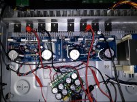
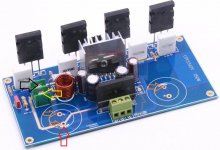
Attached is an old photo of the uPC1342V amplifier in question, however with an different (smaller) rectifier filter board.
The power and output connections are 16 AWG Remington Industries tinned stranded copper wire which is soldered to the bottom of the PCB. (Instead of using the screw terminals supplied in the kit.)
The ALPS potentiometer board is in the very upper left.
The power and output connections are 16 AWG Remington Industries tinned stranded copper wire which is soldered to the bottom of the PCB. (Instead of using the screw terminals supplied in the kit.)
The ALPS potentiometer board is in the very upper left.
Attachments
Last edited:
Attached in order are:
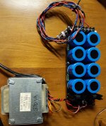
- The current rectifier/filter board and power transformer.
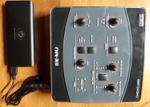
- The E-MU 0404 USB and USB battery pack.
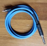
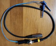
- The TS to RCA cable that connects to the amplifier input.
- The balanced attenuator (built on the TRS jack) to XLR for the amplifier output.
- The much better measuring MX50X2 amplifier (much better measurements in the same chassis with the same power supply and wiring).
Attachments
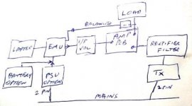
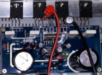
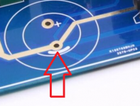
It looks like you have the attached ground related SLD. That assumes there are no other mains supplied equipment connected to anything (eg. like meters)
When the EMU PSU is used, there is a noise loop formed via the mains, and there may also be a noise loop related to the EMU output and input connections.
One aspect may be due to the EMU connections finally getting to the Amp pcb via different ground points on the pcb (ie. the grey arrow input, and the yellow arrow related output).
The other aspect may be due to the amp pcb power input ground point (ie. the red arrow point).
External loops can sometimes be alleviated by restricting connections to the amp pcb to just one star point.
However there are also other parasitic paths that may be an influence, such as the chassis with its capacitive coupling to the Tx and the amp output stage devices (via the heatsink).
Attachments
The only mains connection is the power transformer for the amplifier. Meters are battery powered but were actually disconnected after setting the bias, level, etc.
The grey arrow ground and the yellow arrow ground connect to the star point (red) with their own traces so I thought it was reasonable. All the ground connections on that PCB have their own traces to that star point (red arrow).
Not sure what else to try at this point.
Maybe as a last experiment I will install the rectifier on the uPC1342V amplifier PCB (as intended by the designer) and eliminate the external rectifier and filter board. At that point it will be the closest to an ideal star ground that I think can be done with this kit/PCB.
If it still measures much worse than the MX50X2 then maybe I will replace the TTC5200 and TTA1943 outputs (that came with the uPC1342V kit) with 2SC5200N and 2SA1943N that I bought from Mouser and know are genuine Toshiba. (The same batch which I used to repair the MX50X2 that measures well.) The TTC5200 and TTA1943 look genuine but I am not sure what else to try to get the THD/2nd harmonic closer to datasheet expectations.
Last edited:
Gain Problem or Solder Joint Problem?
The attached are (in order):
When soldering the second parallel 56k feedback resistor over the first I though "that is odd, the solder looks a little grey???" The solder I use is "Kester 24-6337-0027 Solder Roll, Core Size 66, 63/37 Alloy, 0.031" Diameter". I don't remember anything looking grey last year when I assembled this kit. (And I am pretty sure I would notice.)
Is there any chance that these pretty looking golden PCB have some sort of incompatibility/reliability issue with standard 63/37 solder?
Would one expect such a large improvement from halving the gain from 31.1 to 15.5? (From 29 dB gain to 23.8 dB gain?)
While I did not have as good a measurement setup last year the THD did appear to degrade significantly since the initial assembly.
The attached are (in order):
- uPC1342V amplifier remeasured today
- Same with half the gain (another 56k feedback resistor soldered in parallel)
When soldering the second parallel 56k feedback resistor over the first I though "that is odd, the solder looks a little grey???" The solder I use is "Kester 24-6337-0027 Solder Roll, Core Size 66, 63/37 Alloy, 0.031" Diameter". I don't remember anything looking grey last year when I assembled this kit. (And I am pretty sure I would notice.)
Is there any chance that these pretty looking golden PCB have some sort of incompatibility/reliability issue with standard 63/37 solder?
Would one expect such a large improvement from halving the gain from 31.1 to 15.5? (From 29 dB gain to 23.8 dB gain?)
While I did not have as good a measurement setup last year the THD did appear to degrade significantly since the initial assembly.
Attachments
Last edited:
Distortions dropped around 6dB which is exactly as expected with around 6dB more feedback ;-)
Jan
Jan
In general, higher gain will result in higher noise, so if you can get by with the lower setting, that's fine.
I am not sure I can help with the 60Hz harmonics. One possibility is your rectifiers - most amp builders prefer soft recovery rectifiers that tend to generate fewer spikes when switching. Some builders like to put snubber caps across the diodes. You could also have some ringing in the trafo. A scope would help to track this down. Also - what is the ripple on the rails when the amp is loaded? If it is more than a few 10's of millivolts, you may need more capacitance, or the amp may not be doing a good job of rejecting supply noise.
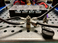
As far as star grounding, there are lots of references in the amp building threads. Attached is a picture of the star ground in one of my amps. The wires come from the PCB grounds and the filter board grounds and are isolated from the chassis. A ground lift thermistor connects the star ground to the chassis. The chassis is connected to AC mains ground.
I am not sure I can help with the 60Hz harmonics. One possibility is your rectifiers - most amp builders prefer soft recovery rectifiers that tend to generate fewer spikes when switching. Some builders like to put snubber caps across the diodes. You could also have some ringing in the trafo. A scope would help to track this down. Also - what is the ripple on the rails when the amp is loaded? If it is more than a few 10's of millivolts, you may need more capacitance, or the amp may not be doing a good job of rejecting supply noise.
As far as star grounding, there are lots of references in the amp building threads. Attached is a picture of the star ground in one of my amps. The wires come from the PCB grounds and the filter board grounds and are isolated from the chassis. A ground lift thermistor connects the star ground to the chassis. The chassis is connected to AC mains ground.
Attachments
Ok. So I wonder why the amplifier needs more feedback a year later? How could it lose gain over one year since initial assembly? (Should I speculate that the THD degraded due to lowered open loop gain? Then when I lowered the closed loop gain by 6 dB the THD went back to expected uPC1342V THD performance but now with the lower gain?)
Could the uPC1342V open loop gain be degrading? (I would not expect so. But I have to wonder where all the new looking "NEC" uPC1342V are coming from for these kits. I thought production ceased long ago.)
Should I re-solder the entire board?
Besides solder joints what should I consider as a potential source of degradation? uPC1342V based amplifiers are fairly simple and do not have many components.
By the way the bias has not moved in one year.
Attachments
Last edited:
As far as star grounding, there are lots of references in the amp building threads. Attached is a picture of the star ground in one of my amps. The wires come from the PCB grounds and the filter board grounds and are isolated from the chassis. A ground lift thermistor connects the star ground to the chassis. The chassis is connected to AC mains ground.
What are the pros and cons of using the thermistor as opposed to the ESP recommendation of a high rectifier power bridge, 10 Ohm and 100nF based ground breaker?
What are the specs/part number for the thermistor?
With the "star ground" obviously designed into the uPC1342V PCB by the designer I assume I should only add a chassis ground wire to the PCB star ground point (red arrow, attached) and attach that to the thermistor or ESP ground breaker.
Attachments

Last edited:
You can use either. I prefer the thermistor approach for class A amps. You can see a typical Nelson Pass PS design in this thread: F6 Illustrated Build Guide
He typically uses CL60 types. Some people even combine bridges with thermistors.
There is a lot of good power supply info in this thread: diyAudio Power Supply Circuit Board v3 illustrated build guide
He typically uses CL60 types. Some people even combine bridges with thermistors.
There is a lot of good power supply info in this thread: diyAudio Power Supply Circuit Board v3 illustrated build guide
I am not sure I can help with the 60Hz harmonics. One possibility is your rectifiers - most amp builders prefer soft recovery rectifiers that tend to generate fewer spikes when switching. Some builders like to put snubber caps across the diodes. You could also have some ringing in the trafo. A scope would help to track this down. Also - what is the ripple on the rails when the amp is loaded? If it is more than a few 10's of millivolts, you may need more capacitance, or the amp may not be doing a good job of rejecting supply noise.
Is it correct to say that the 120Hz is related to the filtering capacitors (capacitance, current draw, frequency) while the 60Hz is magnetic coupling that I might not be able to so much about? (Except perhaps a steel chassis, toroidal transformer and perhaps a steal cover?)
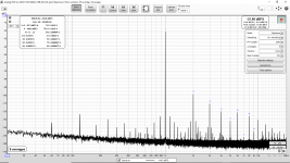
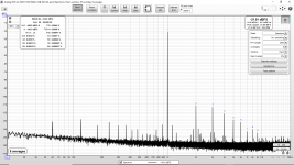
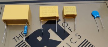
I did some experiments today with the pictured power supply and the pictured capacitors. (Measuring the noise and distortion of the uPC1342V with REW, EBG UXP/300, differential attenuator and E-MU 0404 USB on battery power.)
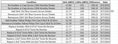
The tabulated results are attached.
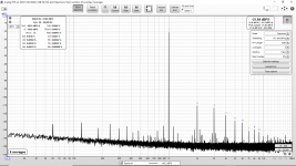
First I placed blue ceramic disk 10nF (measured 8nF) 1kV across the 120A Schottky diodes. That does not appear to make much of a difference in the 120Hz at the output of the uPC1342V amplifier. (I assume this is expected with a Schottky diode not having any minority carrier charge storage.) However of the three repeated measurements two show a small difference and one a large difference. I don't know the reason for that.
Next I placed a snubber across the secondary consisting of a yellow Philips film capacitor (0.56uF) and 10 Ohm metal film. (The first photographed capacitor.) That made a small improvement in the 120Hz.
Then I tried a 0.47uF Tenta K/X2 capacitor instead of the snubber (no resistor). That made a larger improvement in the 120Hz.
Next I tried a 1.0uF Tenta (no resistor) and finally 2x parallel 1.0uF Tenta.
It appears that the "bare" Tenta (no resistor) works much better than the snubber?
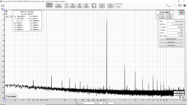
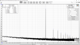
The REW screenshots (attached) correspond to the second line of tabulated data (no added capacitors or snubber) and the last line of tabulated data (10nF disks added across the 120A Schottky diodes and 2x1uF Tenta across the secondary).
Attachments
-
 12 8Vrms EBG Load 0404 Bat Laptop Mains 120A Schottky BC 2x1uF Tenta 10nF 1kV Across Diodes Repe.png148 KB · Views: 388
 -
 1 8Vrms Remeasure EBG Load 0404 Bat Laptop Mains 120A Schottky BC No Snubber No 4p7nF.png166.6 KB · Views: 407
 -
 2021 09 07 Snubber and Capacitor Experiments Summary.png79.2 KB · Views: 383
 -
 20210907_121254.jpg410.8 KB · Views: 325
 -
 20210905_215934.jpg676.9 KB · Views: 331
Last edited:
Good work. I would also suggest shortening those (what appear to be) long wires from the output of the cap board and putting some hefty electrolytic caps on the amp boards in the empty pads. Local decoupling will help a lot.
Also, if you really want to delve into the mysterious world of snubbers 🙂)), take a look at Mark Johnson's Quasimodo test jig:
Simple, no-math transformer snubber using Quasimodo test-jig
Also, if you really want to delve into the mysterious world of snubbers 🙂)), take a look at Mark Johnson's Quasimodo test jig:
Simple, no-math transformer snubber using Quasimodo test-jig
Has anyone used REW to look at the THD and noise of a low distortion amplifier with and without a linear regulator?
Perhaps like the one picture? (Linear Parallel Regulator NAIM NAP250?)
If anyone has please post the measurements. I am wondering what I might gain by using such a regulator with any of my best project amplifiers. (Such as the uPC1342V (blameless), MX50X2, QUAD405-2 and MA9S2.)
Perhaps like the one picture? (Linear Parallel Regulator NAIM NAP250?)
If anyone has please post the measurements. I am wondering what I might gain by using such a regulator with any of my best project amplifiers. (Such as the uPC1342V (blameless), MX50X2, QUAD405-2 and MA9S2.)
Attachments
Tom Christiansen did. He concluded that if you have a super duper spectacularly great amplifier, there is no measurable difference in amp THD between regulated and unregulated supplies ... ... ... provided that both of those supplies have very low output impedance. Super low ESR caps, wide thick traces ("planes and pours"), beefy connectors, short wires, and low ESL caps right at the output device pins on the amplifier board.
The limiting factor turned out to be the impedance of the wires that run between the standalone power supply PCB, and the two amplifier channel PCBs. And by "impedance" I mean "inductive reactance" of course. So amplifiers that eschew a separate power supply board, and put the power supply on the same board as the amplifier itself (example: the AB100 here on diyAudio) have a big advantage.
_
Last edited:
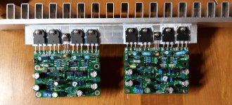
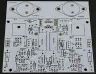
So the pictured uPC1342V boards are perhaps in the right direction with the filter caps and rectifier on the PCB. That said it is only one pair of caps.
Perhaps with only one pair of caps it is even more important to invest in large and low impedance filter caps.
Perhaps with only one pair of caps it is even more important to invest in large and low impedance filter caps.
Attachments

Measuring Best THD and Noise With Stereo Amplifier
So I might have found something that explains why I measured better performance last year when I first assembled the uPC1342V.
Initially I was measuring a single amplifier, not two PCB assembled in one chassis with one power supply, one input connector board and one potentiometer board.
As it turns out, I appear to measure the best THD and noise (including mains harmonics) if I disconnect the input (just the input, not the power supply connections) of the second amplifier from the potentiometer board while I measure the first amplifer.
The attached measurements (REW, E-MU 0404 USB on Battery Pack, EBG UXP/300 Load) are (in order):
There is no signal applied to the right channel.
Can you suggest the best input wiring (including the rca connectors, wiring to the potentiometer board and then from potentiometer board to the two amplifier boards) to avoid this problem? Or do I need to have either two power supplies or even two mono blocks to avoid this? (To avoid the THD increase and the increased power line/mains harmonics.)
My input wiring is as follows:
So I might have found something that explains why I measured better performance last year when I first assembled the uPC1342V.
Initially I was measuring a single amplifier, not two PCB assembled in one chassis with one power supply, one input connector board and one potentiometer board.
As it turns out, I appear to measure the best THD and noise (including mains harmonics) if I disconnect the input (just the input, not the power supply connections) of the second amplifier from the potentiometer board while I measure the first amplifer.
The attached measurements (REW, E-MU 0404 USB on Battery Pack, EBG UXP/300 Load) are (in order):
- Left Side - Measured With Right Input Disconnected & Terminated
- Left Side - Measured With Right Input Connected Normally (much worse)
- Left Side - Measured With Right Input Disconnected & Terminated
- Left Side - Measured With Right Input Disconnected Not Terminated
There is no signal applied to the right channel.
Can you suggest the best input wiring (including the rca connectors, wiring to the potentiometer board and then from potentiometer board to the two amplifier boards) to avoid this problem? Or do I need to have either two power supplies or even two mono blocks to avoid this? (To avoid the THD increase and the increased power line/mains harmonics.)
My input wiring is as follows:
- Input board with 2xRCA (ground joined for left and right)
- "Rapco CM Rated Installation Grade Mic Cable" between the input and potentiometer boards
- Alps RH27 potentiometer board (stereo) but ground joined
- Two individual wires from potentiometer board to the two uPC1342V amplifier board (Again Rapco CM Rated Installation Grade Mic Cable)
Attachments
-
 8Vrms Far Side Short Wiring Other Side Terminated 8x256k.png141.4 KB · Views: 143
 -
 8Vrms Far Side Short Wiring Other Side Reconnected 8x256k.png144.7 KB · Views: 139
 -
 8Vrms Far Side Short Wiring Other Side Disconnected and Terminated Again 8x256k.png141 KB · Views: 115
 -
 8Vrms Far Side Short Wiring Other Side Disconnected and Not Terminated 8x256k.png140.8 KB · Views: 134
 -
 Old uPC1342V Photo Different Rectifier Board.jpg977.5 KB · Views: 134
 -
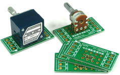 Potentiometer Board.png867.6 KB · Views: 148
 -
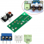 Input Board.png699.1 KB · Views: 136
 -
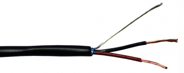 Input Wire Type.png94.7 KB · Views: 130
Last edited:
Is a ground loop unavoidable when assembling a stereo amplifier from two separate mono amplifier boards and a single power supply? The grounds of both amplifiers being connected together first at the single power supply board and then connected together again a second time at the source through the two inputs?
In particular I am asking in regards to the uPC1342V board that is pictured where each of the two boards have a star ground as shown with the red arrow.
At this point I am coming to the conclusion that there is no way around this. Does anyone know of a solution? (Other than two power supplies?) The chassis came with a nice transformer but only one secondary. It appears that the solution is either two transformers, two secondaries or two mono-blocks. Is that right? I guess this PCB layout is only really suitable for mono-blocks.
Attachments
I could comment that noise/hum can result from both mains loops related to galvanic (PE) and transformer coupled signals. As such, the type of power transformer on your amp, and on any signal input equipment that is mains powered, can be complicit - but strangely many people just choose a transformer based on its voltage and current parameters and don't notice or try and measure other aspects of performance that relate to isolation and containment of hum related signals or suppression of leakage inductances.
One aspect of using measuring equipment with better definition of noise floor and hum artefacts is that you may dig your own hole in trying to suppress identifiable hum artefacts, as those artefacts may have significantly lower levels than any music content (including harmonic and IM distortions), and hence are not really a technical problem requiring a solution per se.
One aspect of using measuring equipment with better definition of noise floor and hum artefacts is that you may dig your own hole in trying to suppress identifiable hum artefacts, as those artefacts may have significantly lower levels than any music content (including harmonic and IM distortions), and hence are not really a technical problem requiring a solution per se.
Last edited:
Yes, could be true. However after the effort I invested into the ES9038Q2M and PCM1794A I would like to make the following power amplifier the best I can.One aspect of using measuring equipment with better definition of noise floor and hum artefacts is that you may dig your own hole in trying to suppress identifiable hum artefacts, as those artefacts may have significantly lower levels than any music content (including harmonic and IM distortions), and hence are not really a technical problem requiring a solution per se.
And I just don't like seeing those mains harmonics jump up and seeing the THD double from 0.002% to 0.004%. But yes, those are small numbers/low levels.
I think I will simply wrap up the uPC1342V by putting each amplifier in a separate case (as mono-blocks). In that configuration the THD is 0.002% and the mains/line harmonics are pretty much invisible even with the E-MU 0404 on battery power. So I guess I will call that "good enough" 🙂
I just bought a Tascam US-1x2HR for measurements.
The US-1x2HR version has convenient RCA in and outputs on the back.
Here's the result of a 192k self test.
It looks very good 🙂
The US-1x2HR version has convenient RCA in and outputs on the back.
Here's the result of a 192k self test.
It looks very good 🙂
Attachments
Last edited:
- Home
- Design & Build
- Software Tools
- How to - Distortion Measurements with REW