I said it was like a DAC filter which might have been unclear, getting nyquist ringing in virtual audio manipulation is all too easily done.There's definitely some energy before the peak though (at about 22 KHz)...
There's no DAC involved, as it is all sims.
I know, but we are not the only people reading/writing here so I just wanted to make clear that there wasn't any real signal chain involved.
I don't expect every reader here knowing about my simming streak 😉.
(plus the trick in REW I showed might help others find pré-ringing levels, as said: a true Dirac pulse will show nothing)
I don't expect every reader here knowing about my simming streak 😉.
(plus the trick in REW I showed might help others find pré-ringing levels, as said: a true Dirac pulse will show nothing)
Last edited:
I think I have manual sample rate support working now.
I have been experimenting with colormaps and display issues.
I added a 0 degree plot generation to view the pre/post ringing on both sides at once. Can also see the "linear" alignment of the wave. It now dumps out 3 plots, Formation, 0 degree and Decay.
Each plot has descriptive labels as well.
As resolution increases the mesh color tends to dominate the image, so I am trying to find a ubiquitous solution for that.
What kind of correction do you use here? It seems like the corrected pulse has high levels of pré-ringing. Have you tried one of the various templates linked in the first post of this thread?
What kind of correction do you use here? It seems like the corrected pulse has high levels of pré-ringing. Have you tried one of the various templates linked in the first post of this thread?
I haven't listened to this correction filter. It was created to test the plotting code modifications.
I used DRC-Designer, slammed a few sliders to the extremes to generate the most contrast between the Uncorrected/Corrected test plots. I then generated the test filters in different sample rates to test multiple sample rates plots. The code originally only supported 44100.
I modified the DRC-Designer generated *.bat scripts to capture the intermediate files which required hand editing the soft.drc files to force the intermediate output file creations and switched some of the flags that I read about in this thread to Linear Phase while I was in there.
I added waterfall plots and am parameterizing the code in the attempt to optionally plot 1, 2 or 3 plots per page next. The original code was cut-and-paste rubber-stamped to create each plot which made its size very large and tough to see the pertinent deltas between plots. I am trying to make it table driven with reuseable functions so it is easier to add new plots without copying and pasting a hundred lines of code at a time.
I have not used OCTAVE/MATHCAD before so I am learning the syntax as I go and hopefully learning more about the math/functions/paremeters used to generate the plots in the process.
That explains a lot 🙂.
I don't think I've ever seen that much pré-ringing.
The Octave plots show a limited resolution, to be honest. They can probably show much more, but the scripting that is used is robbing them of the real details i.m.h.o.
The difference between them, and the same info as seen in REW for instance is pretty big. With some work, I'm sure that can be rectified. The comments in the DRC supplied scrips are pretty clear in where they scale it down to make it faster/less taxing I guess.
I had not used it before either, I guess it could be turned into a very useful tool. I'll stick to REW for now, but it looks like you're having fun with it 🙂.
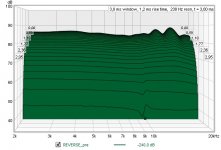
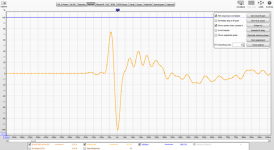
For instance, this graph I showed earlier:
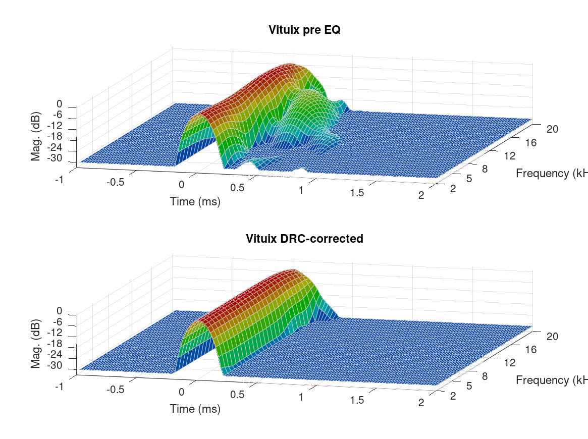
could be compared to a waterfall plot using similar settings within REW:
Before correction:

After correction:
I know which one I prefer right now. 😉 It uses the exact same IR in both cases.
I don't think I've ever seen that much pré-ringing.
The Octave plots show a limited resolution, to be honest. They can probably show much more, but the scripting that is used is robbing them of the real details i.m.h.o.
The difference between them, and the same info as seen in REW for instance is pretty big. With some work, I'm sure that can be rectified. The comments in the DRC supplied scrips are pretty clear in where they scale it down to make it faster/less taxing I guess.
I had not used it before either, I guess it could be turned into a very useful tool. I'll stick to REW for now, but it looks like you're having fun with it 🙂.
For instance, this graph I showed earlier:
could be compared to a waterfall plot using similar settings within REW:
Before correction:
After correction:
I know which one I prefer right now. 😉 It uses the exact same IR in both cases.
Attachments

Last edited:
That is a great result. Is that near field or listening position ?
I am making headway on changing the code to optionally output [1 to N] plots per page so the same code can handle multiple display options. Maybe it can be configured to increase resolution as the number of plots/page diminish.
I use REW as well, but it would still be cool to have a tool that can automatically blueprint a set of IRs.
It's not a measured plot (yet), just a trial run of a DRC-FIR template i'm working on which I ran on a Vituixcad sim. Simulations have made me reconsider some of my DSP tactics.
I can see your goal, it would make for a helpful tool. I'd settle for a REW style waterfall plot that would show me the pré-pulse data, that would make me a happy man. Not only for checking pré-ringing, but also for other experiments like cross talk cancellation.
I can see your goal, it would make for a helpful tool. I'd settle for a REW style waterfall plot that would show me the pré-pulse data, that would make me a happy man. Not only for checking pré-ringing, but also for other experiments like cross talk cancellation.
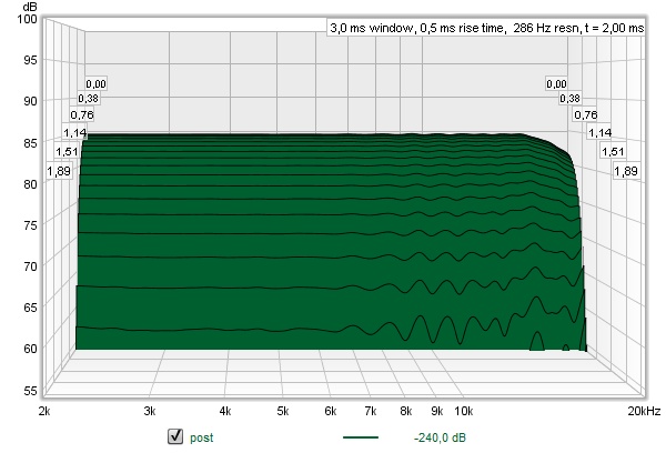
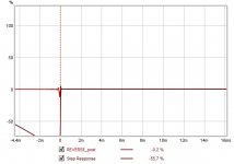
Seek and you shall find (lol)...
I figured all I'd need is to reverse the audio file and load that into REW. So a quick search gave me this site: Reverse Audio - Audioalter
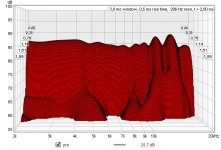
The reversed Pré IR:

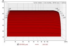
Post IR:

Waterfall plot of the other side of the pré IR:

(notice the 50 dB scale)
And the post convolution IR:

So a simple tool like that would give me all I need... 🙂 A clear view of the other side of the impulse. Now why didn't I think about that any time sooner!
I figured all I'd need is to reverse the audio file and load that into REW. So a quick search gave me this site: Reverse Audio - Audioalter
The reversed Pré IR:
Post IR:
Waterfall plot of the other side of the pré IR:
(notice the 50 dB scale)
And the post convolution IR:
So a simple tool like that would give me all I need... 🙂 A clear view of the other side of the impulse. Now why didn't I think about that any time sooner!
Attachments

FWIW, here is an actual listening position in-room measured response from a RePhase/REW filter. I am hoping DRC-FIR ca do it faster.

The code is now producing [1-n] plots per page. Single plots per page can present more detail when enabled. Higher details in multiple plots per page cause clutter so I am trying to reasonably disable some details in those instances to reduce clutter (e.g. turn off front-2-back grid lines they don't dominate the plot).
Now to rerun all of the plots against the baseline code to make sure I didn't mess up any of the math.

Here is the new waterfall plot. It can be dumped front or back by just specifying the rotation angle.

Now to rerun all of the plots against the baseline code to make sure I didn't mess up any of the math.
Here is the new waterfall plot. It can be dumped front or back by just specifying the rotation angle.
Last edited:
FWIW, here is an actual listening position in-room measured response from a RePhase/REW filter. I am hoping DRC-FIR ca do it faster.
I don't know about faster, as one can get lost in the many variables from DRC, but in my experiments with both programs, DRC could do a much cleaner job than I ever could by hand using RePhase/REW.
Much cleaner impulse and an excellent correction. The frequency dependent window used by DRC-FIR is way more detailed at similar lengths than the one used in REW. In my humble opinion, it is that frequency dependent window that makes DRC-FIR a strong tool. I've spend a lot of time just adjusting that window size (and shape) and analyzing what effect it had (for me, subjectively) in perception. I'd recommend playing with that feature, which would be easy to do using DRC-Designer.
Based on those tests I created my own templates and batch files to be able to adjust them for my specific goal to fit the impulse correction of floor to ceiling arrays.
(which is a very different requirement from the usual single or multi-way speakers)
OCTAVE Vector Outputs
One quick note, you can specify the DPI "-r600" (default is "-r150") to increase the image size/resolution for bitmap based outputs (e.g. ".png", ".jpg") or output to vector based formats such as ".pdf" to preserve resolution and zooming capabilities.
One quick note, you can specify the DPI "-r600" (default is "-r150") to increase the image size/resolution for bitmap based outputs (e.g. ".png", ".jpg") or output to vector based formats such as ".pdf" to preserve resolution and zooming capabilities.
Hello,
I had a few questions that I was hoping to get answered. I think I have gone though this whole thread at this point and still had a few questions.
Some are about DRC in general and some are more about DRC Designer
1) I am more trying to get people opinion on this one. But is DRC Designer a good way to get ones feet wet and get 95% of the way there? Or should I really just cut to the chase and learn it through the way outlined here by gmad?
I have a 7.2 setup but am mainly looking to improve my stereo music listening. So I run my PC AVR (which looks after bass management and crossover at 100hz) L&R HTM-12s (they have a woofer and a compression driver) and to a behringer amp that has its own PEQ of dual 18” subs. So would that be simple enough for DRC Designer? Or should I deep dive into the method outlined here by gmad? More so looking for opinions on this one.
2) My understanding is that even if the initial recording is done in REW with the mic calibration in REW that it also needs to be loaded into DRC correct?
If that is the case, I tried to edit my mic calibration text file to follow the required formatting but this is the error that I receive through DRC Designer:
“Reading mic compensation definition file: E:\John\Audio - HiFi\REW\UMIK-1\7060719_90deg - DRC.txt
Mic compensation direct inversion.
Allocating mic compensation filter arrays.
Mic compensation FIR Filter computation...
FIR Filter computation failed.”
Any ideas what I am doing wrong? Or do I need to even worry about this if I do my initial recording in REW with its mic calibration activated?
3) Should I do my baseline / raw measurements with or without my pre-existing parametric EQ in place? I spent a bit of time making a combination of nearfield gated measurements and then MMM in room measurements to create a quite good sounding PEQ file that I have been using and really enjoying. I have since become interested in DRC and thus I am wondering if it would work best if I ‘layered’ DRC ontop of the existing EQ or if I should start from the ground up and just measure the raw speaker/sub response with no EQ. Really the question is, if one wants to add PEQ should they do it pre or post DRC?
4) Is there any easy way to make correction files for surround channels and also for the LFE/Sub channel? I am mostly going to use if for stereo listening but I know the upgrade bug will bite at some point. So could I just record them in REW and then export and label them as if they are left or right channels and then when I get the correction files then rename / assign them back to their actual channel? Do people do multichannel EQ with DRC and what’s the best approach for that?
5) Can I use Equalizer APO as a convolver? As it looks like DRC Designer puts output convolver WAV files in “ConvolverFilters” file, so can I use these and import them into into EAPO? Is that adequate? Sorry it is just unclear how Convolver VST fits into the system flow and if it is needed if one uses EAPO?
Thanks for any input and replies! Looking forward to learning more about DRC and trying it out!
I say use gmad's scripts they are very easy to use and there is a complete user guide to walk you through it. You can then change any parameter that DRC has available and gives you the most flexibility and options.Or should I really just cut to the chase and learn it through the way outlined here by gmad?
Yes the mic calibration in REW is only applied to the visible frequency response trace it is not embedded in the impulse when exported.2) My understanding is that even if the initial recording is done in REW with the mic calibration in REW that it also needs to be loaded into DRC correct?
The format of the mic file is very picky if you have too many spaces between the two columns or don't follow the format exactly it will fail. I have attached my file for comparison. It is needed if you want to account for your microphone. If you had a class 1 mic that is naturally flat you could go without if measuring on axis but most mics deviate quite a lot at high frequencies.Any ideas what I am doing wrong? Or do I need to even worry about this if I do my initial recording in REW with its mic calibration activated?
If you intend to keep the PEQ in the chain then you need to measure with it in. Sometimes it is helpful to use some pre EQ to get the basic response closer to the intended target as DRC will only correct within a certain range. I use it with my setup as the line array needs a lot of EQ to be corrected. You can always try it both ways and see if it makes a difference for you.3) Should I do my baseline / raw measurements with or without my pre-existing parametric EQ in place? I spent a bit of time making a combination of nearfield gated measurements and then MMM in room measurements to create a quite good sounding PEQ file that I have been using and really enjoying. I have since become interested in DRC and thus I am wondering if it would work best if I ‘layered’ DRC ontop of the existing EQ or if I should start from the ground up and just measure the raw speaker/sub response with no EQ. Really the question is, if one wants to add PEQ should they do it pre or post DRC?
You can create correction files for any speakers you have separately. There is no need to process them as left and right you can make a new script to just process them one at a time.4) Is there any easy way to make correction files for surround channels and also for the LFE/Sub channel? I am mostly going to use if for stereo listening but I know the upgrade bug will bite at some point. So could I just record them in REW and then export and label them as if they are left or right channels and then when I get the correction files then rename / assign them back to their actual channel? Do people do multichannel EQ with DRC and what’s the best approach for that?
You probably can but I don't know it can do multichannel convolution, I have never used it.5) Can I use Equalizer APO as a convolver? As it looks like DRC Designer puts output convolver WAV files in “ConvolverFilters” file, so can I use these and import them into into EAPO? Is that adequate? Sorry it is just unclear how Convolver VST fits into the system flow and if it is needed if one uses EAPO?
I use Jriver which is very flexible. Multichannel convolution is run with a text file to allocate the correct convolution files to the channels. It can also host VST plugins which allows for a multitude of options.
ConvolverVST is a plugin that would need to be run in a VST host of some kind.
Attachments
You can create correction files for any speakers you have separately. There is no need to process them as left and right you can make a new script to just process them one at a time.
True, but measuring them separately might mean treating them as a left or right channel (temporary) inside the measurement chain.
ConvolverVST uses the same text file structure to handle multi-channel convolution.
5) Can I use Equalizer APO as a convolver? As it looks like DRC Designer puts output convolver WAV files in “ConvolverFilters” file, so can I use these and import them into into EAPO? Is that adequate? Sorry it is just unclear how Convolver VST fits into the system flow and if it is needed if one uses EAPO?
Equalizer APO has an in-built convolver, you don't need an extra plugin.
Ok, thanks everyone for all the feedback, I truly do appreciate it! I am vert excited to start toying around with DRC for sure!
Resolved issues:
Mic calibration:
Yes it is very picky formatting, thanks fluid for the guidance. The problem was my mic calibration started at 10db and not 0db and ran to 20,000 not 22,050. So I just had to add the line
0 0 at the start and 22050 0 at the end and it worked like a charm!
Equalizer APO:
I got Equalizer APO to work I think?!
Below is a screen capture for a very generic response made from DRC Designer just to prove to myself that it works.
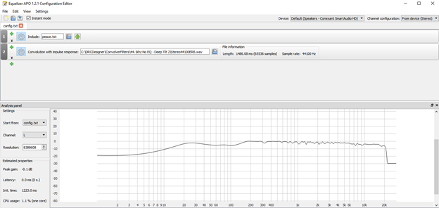
I think EAPO has a VST Plugin but I could not get it to work but it seems that the loading the .WAV as the convolution impulse response works fine so no need to tinker with the VST plugin I suspect.
DRC Designer:
I got DRC Designer to start working! But yeah I think I will want the flexibility of the scripts from gmad and others, so I will have to dig into those scrips a bit more.
New Questions:
1) Measuring in REW:
Does increasing the sweep length have any benefit? I know that the guide says do a long sweep (1M = ~22s), but REW also allows for 2M and 4M = 87s sweeps so would there be any benefit to doing that?
Also, I know that lots of room correction software and also RePhase say one should do numerous measurements and then align and then average them. Is there any benefit in doing that? Seems rather impressive if DRC truly only needs 1 measurement, but I am more than happy to do more measurements if that results in greater results.
2) Changing .wav impulse to .pcm
I cannot find an easy way for Audacity to export as .pcm and thus am using Cool Edits Pro as that was suggested as a potential program from percevals guide in post #9. So is there any need to use audacity at all?
I measure and export from REW, change impulse .wav to .pcm with Cool Edits and put in the drc “sample folder” and then run various scrips and then load the convolver filters into Equalizer APO as my convolver. Is this general workflow correct?
3) IR Stereo vs Mono
I am just making sure that I am not messing up this step.
The guide says “Open the impulse response wave file using Audacity. If it was determined that the impulse center of each measurment was indeed the loudest peak, split the stereo track into two separate mono tracks (choose "Split Stereo to Mono" from the track dropdown menu) and export the tracks as separate files in RAW 32 bit float format (File - Export Multiple etc...).”
But are we not supposed to take separate L&R measurements and then export them as mono as per percevals guide in post #9 and thus there are no tracks to separate?
Anyways I am just making sure as it did not seem like I needed to do this step as the impulse response is already a mono file from REW.
4) IR Timing
My impulse response is just slightly off from 0 as it identifies the downward component as the larger peak and thus the impulse center.
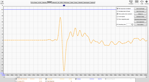
Will this be an issue? Or should I tell DRC where the impulse center is?
I could not figure out how to make Audacity display the information, so I just used REW to “Show points when zoomed in” and then count back from the sample rate
So 44100 – 2 = 44098 is what I should put in "BCImpulseCenter" and then put "BCImpulseCenterMode" as “M” does this seem correct?
5) Test Filters:
I saw that the ___Test scripts generates filters that can be imported into REW, is this accurate enough for quick a dirty evaluation of each custom filter and the changes it makes? Seems very valuable that you don’t have to re-measure after every single change and thus allows for a lot more tinkering.
6) Tinkering with scripts:
It looks like the scripts reference and run off of the .drc files that are in the drc-3.2.2/sample folder correct? So if we want to tinker, then those are the .drc files that we should play around with and edit as a text file.
7) Phase / time alignment
I am most interested in time / phase aligning the low end of my system and I read in post #407
“I think the easiest way to do it would be to start with the custom script and make the following edits:
EPLowerWindow = 35280
EPUpperWindow = 35
EPFinalWindow = 35280
PLMaxGain = 0.1
This will flatten the phase response with minimal impact on the freq response. Pre-ringing will be limited to 4 cycles (which is a lot). If excessive pre-ringing is an issue for your particular application, change the values of RTLowerWindow and RTUpperWindow to 8820 and 9, or 4410 and 4 respectively.”
If latency would not bother me, then would these also be the parameters that I could use / start from?
Or does anyone have other suggestions.
If I wanted to change those above numbers then should take into account the sample rate or can I really do any old number?
Does the number of taps come from these parameters or is there another line that needs to be edited to indicate the number of taps.
Thank again for all the input and help!
Resolved issues:
Mic calibration:
Yes it is very picky formatting, thanks fluid for the guidance. The problem was my mic calibration started at 10db and not 0db and ran to 20,000 not 22,050. So I just had to add the line
0 0 at the start and 22050 0 at the end and it worked like a charm!
Equalizer APO:
I got Equalizer APO to work I think?!
Below is a screen capture for a very generic response made from DRC Designer just to prove to myself that it works.
I think EAPO has a VST Plugin but I could not get it to work but it seems that the loading the .WAV as the convolution impulse response works fine so no need to tinker with the VST plugin I suspect.
DRC Designer:
I got DRC Designer to start working! But yeah I think I will want the flexibility of the scripts from gmad and others, so I will have to dig into those scrips a bit more.
New Questions:
1) Measuring in REW:
Does increasing the sweep length have any benefit? I know that the guide says do a long sweep (1M = ~22s), but REW also allows for 2M and 4M = 87s sweeps so would there be any benefit to doing that?
Also, I know that lots of room correction software and also RePhase say one should do numerous measurements and then align and then average them. Is there any benefit in doing that? Seems rather impressive if DRC truly only needs 1 measurement, but I am more than happy to do more measurements if that results in greater results.
2) Changing .wav impulse to .pcm
I cannot find an easy way for Audacity to export as .pcm and thus am using Cool Edits Pro as that was suggested as a potential program from percevals guide in post #9. So is there any need to use audacity at all?
I measure and export from REW, change impulse .wav to .pcm with Cool Edits and put in the drc “sample folder” and then run various scrips and then load the convolver filters into Equalizer APO as my convolver. Is this general workflow correct?
3) IR Stereo vs Mono
I am just making sure that I am not messing up this step.
The guide says “Open the impulse response wave file using Audacity. If it was determined that the impulse center of each measurment was indeed the loudest peak, split the stereo track into two separate mono tracks (choose "Split Stereo to Mono" from the track dropdown menu) and export the tracks as separate files in RAW 32 bit float format (File - Export Multiple etc...).”
But are we not supposed to take separate L&R measurements and then export them as mono as per percevals guide in post #9 and thus there are no tracks to separate?
Anyways I am just making sure as it did not seem like I needed to do this step as the impulse response is already a mono file from REW.
4) IR Timing
My impulse response is just slightly off from 0 as it identifies the downward component as the larger peak and thus the impulse center.
Will this be an issue? Or should I tell DRC where the impulse center is?
I could not figure out how to make Audacity display the information, so I just used REW to “Show points when zoomed in” and then count back from the sample rate
So 44100 – 2 = 44098 is what I should put in "BCImpulseCenter" and then put "BCImpulseCenterMode" as “M” does this seem correct?
5) Test Filters:
I saw that the ___Test scripts generates filters that can be imported into REW, is this accurate enough for quick a dirty evaluation of each custom filter and the changes it makes? Seems very valuable that you don’t have to re-measure after every single change and thus allows for a lot more tinkering.
6) Tinkering with scripts:
It looks like the scripts reference and run off of the .drc files that are in the drc-3.2.2/sample folder correct? So if we want to tinker, then those are the .drc files that we should play around with and edit as a text file.
7) Phase / time alignment
I am most interested in time / phase aligning the low end of my system and I read in post #407
“I think the easiest way to do it would be to start with the custom script and make the following edits:
EPLowerWindow = 35280
EPUpperWindow = 35
EPFinalWindow = 35280
PLMaxGain = 0.1
This will flatten the phase response with minimal impact on the freq response. Pre-ringing will be limited to 4 cycles (which is a lot). If excessive pre-ringing is an issue for your particular application, change the values of RTLowerWindow and RTUpperWindow to 8820 and 9, or 4410 and 4 respectively.”
If latency would not bother me, then would these also be the parameters that I could use / start from?
Or does anyone have other suggestions.
If I wanted to change those above numbers then should take into account the sample rate or can I really do any old number?
Does the number of taps come from these parameters or is there another line that needs to be edited to indicate the number of taps.
Thank again for all the input and help!
Attachments

Last edited:
It makes the measurement more immune to outside noise. If the sweep is too long it can cause items in your room and structure to rattle. I think 1m is enough in most cases.New Questions:
1) Measuring in REW:
Does increasing the sweep length have any benefit?
Vector averaging can work out well in a reverberant room or where you want to achieve a better balance across multiple seats. The problem with that is that is it will not be ideal anywhere. I suggest to try it both ways and find out if you prefer one over the other.Also, I know that lots of room correction software and also RePhase say one should do numerous measurements and then align and then average them. Is there any benefit in doing that? Seems rather impressive if DRC truly only needs 1 measurement, but I am more than happy to do more measurements if that results in greater results.
That is simple you export the audio as raw 32 bit float and then change the extension to .pcm manually as Audacity uses .raw2) Changing .wav impulse to .pcm
I cannot find an easy way for Audacity to export as .pcm
If you have separate mono responses they can be used as is. There is only a need to split them if they are combined already, which is possible with REW. It is easier to leave them separate as far as I am concerned.3) IR Stereo vs Mono
Anyways I am just making sure as it did not seem like I needed to do this step as the impulse response is already a mono file from REW.
The 100% peak is almost always the actual impulse centre unless somehow you have a very early reflection that is higher than the direct sound. I would check the polarity of the system as it could well be reversed somewhere. If you leave impulse centre as Auto DRC will find it and use it.4) IR Timing
My impulse response is just slightly off from 0 as it identifies the downward component as the larger peak and thus the impulse center.
Yes 🙂5) Test Filters:
I saw that the ___Test scripts generates filters that can be imported into REW, is this accurate enough for quick a dirty evaluation of each custom filter and the changes it makes? Seems very valuable that you don’t have to re-measure after every single change and thus allows for a lot more tinkering.
You can have one base .drc file and then create different batch scripts to change the parameters. Whatever is in the batch script with the -- flag before it will override the base file.6) Tinkering with scripts:
It looks like the scripts reference and run off of the .drc files that are in the drc-3.2.2/sample folder correct? So if we want to tinker, then those are the .drc files that we should play around with and edit as a text file.
That is quite a lot of excess phase correction. By all means try it and see.7) Phase / time alignment
EPLowerWindow = 35280
EPUpperWindow = 35
EPFinalWindow = 35280
PLMaxGain = 0.1
Or does anyone have other suggestions.
If I wanted to change those above numbers then should take into account the sample rate or can I really do any old number?
Does the number of taps come from these parameters or is there another line that needs to be edited to indicate the number of taps.
Code:
--EPWindowGap=32 --EPLowerWindow=1366 --EPPFFinalWindow=1366 --EPUpperWindow=32
 --EPWindowExponent=0.97 --ISPELowerWindow=6547 --ISPEUpperWindow=400
The above is what I use.
PSOutWindow is the length of the filter for linear phase and
MSOutWindow does the same for minimum phase. You can use both in one file if you want.
Attachments

Ok! I think I got it up and running!
Thanks for the help everyone!
I can either change the base .drc file and then just keep the one batch script that runs it, or I can change the batch script and whatever with the "--" before it will override the .drc file correct?
As I am using the first approach (changing the .drc and keeping one base batch script)
Currency my script looks like:
(This is my minimal script)
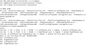
Set DRC_DIR=\Room Correction\drc-3.2.2\sample
Set CONVOLVER=\Room Correction\Convolver Filters
cd %DRC_DIR%
drc.exe --BCInFile=LeftSpeakerImpulseResponse.pcm --PSOutFile=LeftSpeaker-MinimalFilter.pcm minimal-44.1.drc
pause
drc.exe --BCInFile=RightSpeakerImpulseResponse.pcm --PSOutFile=RightSpeaker-MinimalFilter.pcm minimal-44.1.drc
pause
sox.exe -t raw -e float -b 32 -r 44100 -c 1 LeftSpeaker-MinimalFilter.pcm -e signed -t wavpcm LeftSpeaker-MinimalFilter.wav
sox.exe -t raw -e float -b 32 -r 44100 -c 1 RightSpeaker-MinimalFilter.pcm -e signed -t wavpcm RightSpeaker-MinimalFilter.wav
sox.exe -M LeftSpeaker-MinimalFilter.wav RightSpeaker-MinimalFilter.wav -e signed -t wavpcm MinimalFilter.wav
move /y MinimalFilter.wav "%CONVOLVER%
del "LeftSpeaker-MinimalFilter.pcm"
del "RightSpeaker-MinimalFilter.pcm"
del "LeftSpeaker-MinimalFilter.wav"
del "RightSpeaker-MinimalFilter.wav"
and then I edit my .drc file with whatever edits that I want (so in this case I edited my minimal-44.1.drc file in the Room Correction\drc-3.2.2\Sample folder).
This is equivalent and an acceptable work flow is it not?
Also, I have heard lots of people say that getting minimum phase in the bass and longer filter lengths especially help in the bass.
I am mostly looking to get nice tight punchy bass with DRC (and yes some general room correction as well)
Anyways, changing the EPLowerWindow and ISPELowerWindow and EPFinalWindow would be how much low end phase correction it is correcting correct? And then changing the MPWindowExponent and RTWindowExponent is how much it focuses it computation / correction on the low vs high end. So if I primarily want to correct the phase in the bass then I would change the values to less than 1 (1 being linear, 0.2 being heavily weighted toward the low end). Would that be the right way of starting things off?
I am looking forward to hearing peoples suggestions.
Thanks for the help everyone!
Ok I am just making sure that I got this right.You can have one base .drc file and then create different batch scripts to change the parameters. Whatever is in the batch script with the -- flag before it will override the base file.
I can either change the base .drc file and then just keep the one batch script that runs it, or I can change the batch script and whatever with the "--" before it will override the .drc file correct?
As I am using the first approach (changing the .drc and keeping one base batch script)
Currency my script looks like:
(This is my minimal script)
Set DRC_DIR=\Room Correction\drc-3.2.2\sample
Set CONVOLVER=\Room Correction\Convolver Filters
cd %DRC_DIR%
drc.exe --BCInFile=LeftSpeakerImpulseResponse.pcm --PSOutFile=LeftSpeaker-MinimalFilter.pcm minimal-44.1.drc
pause
drc.exe --BCInFile=RightSpeakerImpulseResponse.pcm --PSOutFile=RightSpeaker-MinimalFilter.pcm minimal-44.1.drc
pause
sox.exe -t raw -e float -b 32 -r 44100 -c 1 LeftSpeaker-MinimalFilter.pcm -e signed -t wavpcm LeftSpeaker-MinimalFilter.wav
sox.exe -t raw -e float -b 32 -r 44100 -c 1 RightSpeaker-MinimalFilter.pcm -e signed -t wavpcm RightSpeaker-MinimalFilter.wav
sox.exe -M LeftSpeaker-MinimalFilter.wav RightSpeaker-MinimalFilter.wav -e signed -t wavpcm MinimalFilter.wav
move /y MinimalFilter.wav "%CONVOLVER%
del "LeftSpeaker-MinimalFilter.pcm"
del "RightSpeaker-MinimalFilter.pcm"
del "LeftSpeaker-MinimalFilter.wav"
del "RightSpeaker-MinimalFilter.wav"
and then I edit my .drc file with whatever edits that I want (so in this case I edited my minimal-44.1.drc file in the Room Correction\drc-3.2.2\Sample folder).
This is equivalent and an acceptable work flow is it not?
Also, I have heard lots of people say that getting minimum phase in the bass and longer filter lengths especially help in the bass.
I am mostly looking to get nice tight punchy bass with DRC (and yes some general room correction as well)
Anyways, changing the EPLowerWindow and ISPELowerWindow and EPFinalWindow would be how much low end phase correction it is correcting correct? And then changing the MPWindowExponent and RTWindowExponent is how much it focuses it computation / correction on the low vs high end. So if I primarily want to correct the phase in the bass then I would change the values to less than 1 (1 being linear, 0.2 being heavily weighted toward the low end). Would that be the right way of starting things off?
I am looking forward to hearing peoples suggestions.
- Home
- Loudspeakers
- Full Range
- A convolution based alternative to electrical loudspeaker correction networks