
Fortunately the user manual is very detailed and all modern PC have RS232 port.
What I can't understand, is why you would expect Soekris to respond after how you have acted in this and other threads. And even when asking for help, you persist with the same negative attitude.
Many, many other people have gotten this to work. So that either means you don't know what you are doing, or you have a faulty board. I'm not sure which would be funnier.
I expect support because I have bought the board paying 350 Euro.
There wasn't any negative attitude, I have measured the jitter/phase noise of the clock signals and I have published the plots.
It was objective measurements, nothing more.
If you don't like the measurement results it's not my problem, I'm not the designer.
If you don't trust the reliability of the measurements it's not my problem, you can do the measurements by yourself.
So where is the problem?
I had decided to not waste more time on you, you are extremely rude and irritating, but you're making so much noise on this thread, again, so:
I use J10 when testing, so we can assume that the board worked when leaving me....
TX seem to work, so put a scope on the RX pin, t.ex, on the receiver output at U39 pin 9, and see if there is signal there, or directly and the uC U37 pin20. If not, check your J10 soldering and shorts elsewhere. If there are, check your software settings.
Try with the TTL levels signals at J3.
Many of those USB to Serial adapters are crap, the best are the ones from FTDI, available from t.ex. Digikey and Farnell in both TTL and RS-232 versions....
At least 23 people has managed to do it by simply following the manual.
This stupid noise has all the ingredients of a preemptive strike. Complain about and smear your competitors before launching your own product.
I had decided to not waste more time on you, you are extremely rude and irritating, but you're making so much noise on this thread, again, so:
I use J10 when testing, so we can assume that the board worked when leaving me....
TX seem to work, so put a scope on the RX pin, t.ex, on the receiver output at U39 pin 9, and see if there is signal there, or directly and the uC U37 pin20. If not, check your J10 soldering and shorts elsewhere. If there are, check your software settings.
Try with the TTL levels signals at J3.
Many of those USB to Serial adapters are crap, the best are the ones from FTDI, available from t.ex. Digikey and Farnell in both TTL and RS-232 versions....
It's not quite so.
It seems you like when someone uses sarcasm toward me and when he call me a stupid but you don't like my replies to such posts.
Please, read the last posts.
P.S. just read the last two, I will avoid to reply.
Anyway, thank you for the reply, but:
- I have already checked J10 solderings but ther is no way to get one of my 3 adapters working
- TX and RX seem to work via J3 as in the attached picture
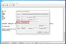
- I'm able to invoke download command (Hyper Terminal screen attached)
- no way to download the filter by XMODEM or XMODEM 1K file transfer. Hyper Terminals says "Got retry request"
So I assume the communication between PC and micro works correctly but Xmodem transfer file fails.
I could check with a scope as you have suggested, but for what purpose?
The communication is settled correctly so I assume I would see correct signals on the scope.
The problem seems to be related exclusively to the Xmodem transfer file.
Maybe a protocol problem?
Attachments
RX works or one wouldn't see
R1.21
I3
L000
etc...
so it must be a user error launching the file transfer...
//
R1.21
I3
L000
etc...
so it must be a user error launching the file transfer...
//
....
The problem seems to be related exclusively to the Xmodem transfer file.
Maybe a protocol problem?
I have used exact same firmware on thousands of boards, also before the dam1021, so lets assume the firmware is good.... Then there is noise or your PC. Try Xmodem 1K or a different/clean computer, you might have software interfering, who knows.
RX works or one wouldn't see
R1.21
I3
L000
etc...
so it must be a user error launching the file transfer...
//
What kind of error?
I have used Tera Term, Extra Putty and Hyper Terminal, Xmodem and Xmodem 1K and all failed.
Is there something to configure in the software?
I have used exact same firmware on thousands of boards, also before the dam1021, so lets assume the firmware is good.... Then there is noise or your PC. Try Xmodem 1K or a different/clean computer, you might have software interfering, who knows.
I have tried Xmodem and Xmodem 1K, I have tried with a pair of PC, both running Win 10.
Tera Term, Extra Putty and Hyper Terminal.
Can you please tell me if there is something to configure software side or hardware adapter side?
@soekris
It is possible to share more information about changes in filters in rev7 and how to implement new. I especially interested is there will be separate blank txt filter file or converter. How to import existing filters, etc.
New 1.24 filter files up on website, also new MKROM.EXE. In order to support new rev7 boards there now is a 1.5Mhz x4 FIR2. You can have both FIR2 filters in the file, like on stock file, the correct one will be used by firmware.
Should be possible to make new filter files, but please note it's not easy and require knowledge of digital filters.
I own rev3 board and I'm trying to use TNT NOS filter without DC HP because I have to play bit perfect DC samples
Filter brewing for the Soekris R2R
So the problem could be the filter file?
Filter brewing for the Soekris R2R
So the problem could be the filter file?
By the way, I also have the 2nd type adapter and I tried to flash my esp8266 chips with it. The normal terminal communication worked, but the firmware download always failed.
I never tried the adapter together with the dam1021. Here I always loaded the firmware via X10, with an adapter similar to the one in the 3rd link.
If most serial adapters are 'crap,' then maybe lowering the baud rate with the 'set' command would improve data transfer reliability?
New 1.24 filter files up on website, also new MKROM.EXE. In order to support new rev7 boards there now is a 1.5Mhz x4 FIR2. You can have both FIR2 filters in the file, like on stock file, the correct one will be used by firmware.
Should be possible to make new filter files, but please note it's not easy and require knowledge of digital filters.
Thank you. Now I understand your approach.
- Home
- Vendor's Bazaar
- Reference DAC Module - Discrete R-2R Sign Magnitude 24 bit 384 KHz