I checked some of my other amps, and similar Zener resistors are running at 50 degrees.
But - they are bigger in size (same power rating 1W), and they are mounted vertically (standing up) which helps cooling.
In the last amp I used new resistors. 1W and small size, so that looked good to me, but I guess it was 'too good' to be true.
But - they are bigger in size (same power rating 1W), and they are mounted vertically (standing up) which helps cooling.
In the last amp I used new resistors. 1W and small size, so that looked good to me, but I guess it was 'too good' to be true.

But possibly more concisely?Sorry for lengthy post, but certain things needed to be said about this amp.
Basically it sounded fine, and even better turned up loud? True of most amps out there (the one's that don't clip, basically), as speakers and acoustics dominate over any coloration from a reasonable amp.
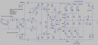
Protecting R17 etc
You may want to consider replacing D3 with a cheap NPN to protect R17 etc. Note that it is both a current limit on Q2 and replaces D3 as a negative clamp. You can divide R17 in two or reduce it for a higher clamp current.
You may want to consider replacing D3 with a cheap NPN to protect R17 etc. Note that it is both a current limit on Q2 and replaces D3 as a negative clamp. You can divide R17 in two or reduce it for a higher clamp current.
Attachments
OP-amp gain
The only way to avoid voltage gain in the op-amp may be to short the output, and maybe none depending on the op-amp internal compensation. But the well matched op-amp input and gain is probably why the amp measure a great THD. But this can lead to the classic TIM and other IPS clipping issues.
Years ago a friend made a communication RX using an op-amp to drive a Schmitt trigger gate. But it did not work at speed because the op-amp clipped all the way to +-12V, which took forever to slew back to logic voltage levels. This is much like your amp but you have better op-amps and you don't have to worry about 20KHz+.
Using a unity gain stable op-amp as a front end means the op-amp dominant pole competes with the VAS pole for dominance. Even without a miller cap on the VAS, it usually falls lower than a modern op-amp so you need to do what you can to move the op-amp pole as high as possible. An externally compensated or minimum gain op-amp might be a good choice. I had no luck finding decompensated versions of common op-amps that I know used to exist but I did find this: https://www.ti.com/lit/an/slyt174/slyt174.pdf
>opamp works only as a buffer here
Apparently not.
See this thread (post #110 and other posts).
Sandro claims that ACTUAL voltage gain happens in the op-amp.
I'm not sure how this can be, as voltage swing at the output of the op-amps is small, but since he is the guy who led AD8450 development, I guess he knows something about op-amps.
I guess it's the combination of all of them: op-amp, buffer after it, AND ccs that actually make voltage gain happen.
The only way to avoid voltage gain in the op-amp may be to short the output, and maybe none depending on the op-amp internal compensation. But the well matched op-amp input and gain is probably why the amp measure a great THD. But this can lead to the classic TIM and other IPS clipping issues.
Years ago a friend made a communication RX using an op-amp to drive a Schmitt trigger gate. But it did not work at speed because the op-amp clipped all the way to +-12V, which took forever to slew back to logic voltage levels. This is much like your amp but you have better op-amps and you don't have to worry about 20KHz+.
Using a unity gain stable op-amp as a front end means the op-amp dominant pole competes with the VAS pole for dominance. Even without a miller cap on the VAS, it usually falls lower than a modern op-amp so you need to do what you can to move the op-amp pole as high as possible. An externally compensated or minimum gain op-amp might be a good choice. I had no luck finding decompensated versions of common op-amps that I know used to exist but I did find this: https://www.ti.com/lit/an/slyt174/slyt174.pdf
But possibly more concisely?
Basically it sounded fine, and even better turned up loud? True of most amps out there (the one's that don't clip, basically), as speakers and acoustics dominate over any coloration from a reasonable amp.
Mark,I hope you didn't take this review seriously..
The amp sounded fine. Nuff said 🙂
Last edited:
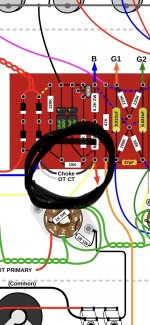
OT CT stands for "Output Transformer Center Tap".
So I guess try to find the transformer first, and then find the center tap.
🙂
So I guess try to find the transformer first, and then find the center tap.
🙂
№1608 It is a rectifier with filter elements. The circuit can be easily reconstructed from the image. You need to look for the external connection diagram.
OT CT stands for "Output Transformer Center Tap".
So I guess try to find the transformer first, and then find the center tap.
🙂
Center from primari ?
Hi, Mr.Minek. I have almost finished layout (#1546), maybe there is a stupid question, I replaced Q2 with TOSHIBA 2SC3423, Q3,Q4 with PHILIPS BF871/BF872. Will my changes affect the stability of the scheme?
2SC3423 should be good.
BFs I don't know.
> Will my changes affect the stability of the scheme?
You are changing EVERY transistor in this schematic, so YES,
all your changes will MOST LIKELY affect stability.
Personally, I would not replace ANY transistors here, without doing thourough simulation with their models.
That's why I publish LTSpice .asc file.
These amps are sensitive.
This amp, with big loop gain and bandwidth, is very easy to oscillate.
Especially with multiple output pairs of mosfets.
BTW - if you are using IRFP outputs, gate stoppers for P and N should have the same value ( E.g. 120 Ohm).
IRFPs have the same or almost the same input capacitance.
Last edited:
№1 VT3,VT4 - " The Rush Vbe multiplier " #65 Towards a wideband non switching Auto Bias power amp
Last edited:
>№1 VT3,VT4 - " The Rush Vbe multiplier " #65 Towards a wideband non switching Auto Bias power amp
Ian H. is driving it from the output, Akulinchev was driving it from driver's output, but it looks very familiar 🙂
https://www.diyaudio.com/forums/sol...wideband-switching-auto-bias-power-amp-7.html
Ian H. is driving it from the output, Akulinchev was driving it from driver's output, but it looks very familiar 🙂
https://www.diyaudio.com/forums/sol...wideband-switching-auto-bias-power-amp-7.html
There seems to be a lot of mistakes in these threads. I dunno how you could expect an LT1166 to work properly by driving it's outputs instead of Vin. I would expect it to fight any drive to the outputs. And one circuit that drives Vin with an op-amp that is powered off the LT1166 outputs is going to see +-40V common mode input with +-4V rails? That may simulate if the op-amp model is over simplified but I'm sure it won't work on real hardware.
"non-switching" invariably costs bandwidth and reliability so I have reservation about the idea. "Auto bias" usually collapses as the signal swings away from the zero crossing, which has to cost some THD. LV has some cool ideas, usually involving sensing the OPS base current, and placing a limit on the bias collapse. An approach I like is to run the drivers class-B, not the slower outputs so that the harmonics are at higher frequencies.
As we get better class-D amps, I have to wonder is better bias for class-AB is a waste of time. But, of course, people continue to drive old cars and listen to vacuum tube amps. Me, I like modern appliances that just work with no fuss or bother. And there are no more great bands like we knew 50 years ago.
@steveu you should probably know that this topology was used in production amps in the 70s.. so obviously it doesnt work :/
Steve, which schematic/post are you referring to?
I see, you are talking about post #5 and #6 - Ian H. simulations.
It looks like the op-amp is floating, like Elvee's current dump amp.
I built the 1st current dump amp (the 'active' one), but I couldn't make the 2nd one ('passive' version) stable...
Last edited:
- Home
- Amplifiers
- Solid State
- Unusual amp from 1987