AC square wave simulation
I notice a couple things.
1. The op-amps in these amps operate with some DC offset from the op-amp output, which will ~avoid AB distortion in certain op-amps.
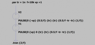
2. The by-pass on the input caps implies you have run into the simulation problem with ~square waves. The best solution I know of is two pulse sources defined with finite rise times as attached. This produces a bipolar ~square wave with time zero value of zero for the sake of the simulation capacitor initial pre-charge.
I notice a couple things.
1. The op-amps in these amps operate with some DC offset from the op-amp output, which will ~avoid AB distortion in certain op-amps.
2. The by-pass on the input caps implies you have run into the simulation problem with ~square waves. The best solution I know of is two pulse sources defined with finite rise times as attached. This produces a bipolar ~square wave with time zero value of zero for the sake of the simulation capacitor initial pre-charge.
Attachments
Thanks Steve, this a good trick...
There was always a problem with simulating square waves, with the cap or without it....
There was always a problem with simulating square waves, with the cap or without it....
>The op-amps in these amps operate with some DC offset from the op-amp output, which will ~avoid AB distortion in certain op-amps.
That's true, now that you mentioned it, I remember that one of the op-amps
was producing DC offset I could see on the oscilloscope, so I didn't even run any test signals for it...
One (or both ?) of these:
LF356 - NO
LT1357 - NO
That's true, now that you mentioned it, I remember that one of the op-amps
was producing DC offset I could see on the oscilloscope, so I didn't even run any test signals for it...
One (or both ?) of these:
LF356 - NO
LT1357 - NO
REDUCTIO AD SIMPLICISSIMAM - REDUCTION TO THE SIMPLEST
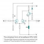
In this post, you presented a possible enhancement of your unusual amp. In Tietze-Schenk book, whereof you quoted earlier, there are some interesting additional ideas. Based on these, I tried to reduce the broadband (current-drive) priciple to the simplest possible practical form. Perhaps it would be worthwhile to build such a circuit with BJT ends and Akulinichev bias circuit.
In this post, you presented a possible enhancement of your unusual amp. In Tietze-Schenk book, whereof you quoted earlier, there are some interesting additional ideas. Based on these, I tried to reduce the broadband (current-drive) priciple to the simplest possible practical form. Perhaps it would be worthwhile to build such a circuit with BJT ends and Akulinichev bias circuit.
Attachments
Last edited:
Unfortunately, without op-amps these amps with simple LTP in the front, do not measure very well (comparing with op-amp based ones).
1st amp from post #54 : op-amp + LTP like in your example above + ccs + mirror to make it symmetrical.
Skip the mirror if no need for push-pull...
Maxim had few designs like this; none of them stable.
He also had few designs without op-amp, just LTP - but they didn't measure that well.
They will be comparable to Vhex or similar amps (judging from my sims).
Last edited:
Unfortunately, without op-amps these amps with simple LTP in the front, do not measure very well (comparing with op-amp based ones).
I see. But not really understand why, opamp works only as a buffer here with small voltage swing.
>opamp works only as a buffer here
Apparently not.
See this thread (post #110 and other posts).
Sandro claims that ACTUAL voltage gain happens in the op-amp.
I'm not sure how this can be, as voltage swing at the output of the op-amps is small, but since he is the guy who led AD8450 development, I guess he knows something about op-amps.
I guess it's the combination of all of them: op-amp, buffer after it, AND ccs that actually make voltage gain happen.
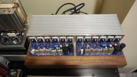
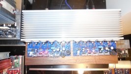
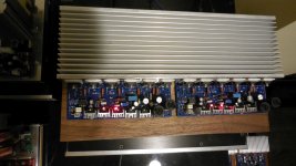
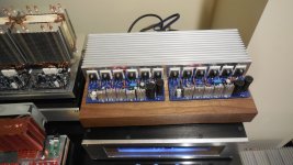
OK, final assembly has been finished, with black walnut chassis. Amp is playing music as we speak.
As usual with good amps, the sound of this amplifier can be described as balanced, detailed, rich and very energetic, and it also features stunning transparency.
Plays cheerful, energetic and organized.
I can hear detail and mobility of the treble all over the place.
For the first test I selected "Lightforce" by Mind.In.a.Box - I'm delighted with its swiftness, clear rhythm, a very large and perfectly structured stage, as well as fun and drive.
2nd masterpiece to enjoy: "Tigana" by Boz & Hazel. Both pieces in the spirit and mood of old C64 tunes.
As far as I can tell - this first LMK-type amp with vertical fets ever.
🙂🙂🙂
Attachments

Last edited:
Thank you for your special and unique review. 😀 BTW, what about the stability of parallel FETs? PS: Great compact PCB. The parts look like generals and soldiers lined up in a military parade. 🙂
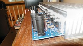
FETs are stable. This amp is running rather warm (50mA idle current per fet).
Voltage on source resistors varies within 20% range.
Voltage on source resistors varies within 20% range.
Daniel,
mind.in.a.box - Lightforce -> seems you have been using a lot of cracks/keygens written with assembler 😀
What a master piece you got there, indeed!
mind.in.a.box - Lightforce -> seems you have been using a lot of cracks/keygens written with assembler 😀
What a master piece you got there, indeed!
As I learned today, R17 (from schematic #1737) (68 Ohm) should be 2W resistor.
When fuse blows on the negative rail (only), it will run at 2W, producing some unpleasant smoke. 🙂
Seems like I need bigger fuses too.
When fuse blows on the negative rail (only), it will run at 2W, producing some unpleasant smoke. 🙂
Seems like I need bigger fuses too.
This is potentially dangerous situation when 1 fuse blows, but not the other one.
I wonder if there is some kind of crowbar contraption, to FORCE the other fuse to blow, in case the first one is blown. So they always go together. This would be safer thing to do.
I wonder if there is some kind of crowbar contraption, to FORCE the other fuse to blow, in case the first one is blown. So they always go together. This would be safer thing to do.
I did it. Nearly same current on both resistor in this case (R17, R10): 178mA. 😱 This is why I wonder how the latter one survived this "adventure".
They both survived, 68 Ohm get little brownish after that, but was still ok.
75 Ohm looked good, and I didn't see any smoke. I guess better quality resistor?
I replaced 68 Ohm resistors with a bigger ones on both channels, just in case.
This was the cause of fuses blowing.
Usually I use 4 amp fuses - on all 100W amps.
I guess this one needs bigger fuses.
75 Ohm looked good, and I didn't see any smoke. I guess better quality resistor?
I replaced 68 Ohm resistors with a bigger ones on both channels, just in case.
This was the cause of fuses blowing.
Usually I use 4 amp fuses - on all 100W amps.
I guess this one needs bigger fuses.
Update: latest amp is running fine.
One subjective observation - _maybe_ it seems to have more bass available than previous amps. More ooomph.
Otherwise - stable, running warm.
Also trebles show even more mobility than I previously thought 🙂
Still the same 4A fuses.
All TO-126 transistors run hot, but not too hot for these small heatsinks.
CCS transistors are hotter than drivers.
Idle current being thermally track just fine. Stable at any temperature so far.
Output DC offset (after few hours): L: 10mV and R: 0.5mV
Last edited:
Great work as usual. My wife has never said about a naked amp that it is "nice." 😀 About a few which were built in a nice case, she said "it could stay". But there is one exception. The AH578 LATFET: "well, it could stay" even if it's naked. 🙂 Need a better recommendation? Maybe she likes the mobility of trebles so much? Who knows...
Last edited:
- Home
- Amplifiers
- Solid State
- Unusual amp from 1987