Diodes usually fail short. If they do, you get a giant phase to phase short. So if you do this don't cheap out on the diodes LOL
put fuses on the phases!
bridges commonly rectify 230V in SMPS
1000V diode bridges should do fine for 380V * 2 = 760V
bridges commonly rectify 230V in SMPS
1000V diode bridges should do fine for 380V * 2 = 760V
put fuses on the phases!
bridges commonly rectify 230V in SMPS
1000V diode bridges should do fine for 380V * 2 = 760V
+ For fuses. But I hope you buy/build a good quality SMPS with good transformer and optocouplers etc. to get proper galvanic isolation. No fun having 400V in your speakers or whatever. I still would consider three 230V/230V transformers for galvanic isolation and safety.
...this seems like it would work....
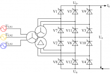
The Y and Y and Delta symbols are transformers. (Or alternators, but he's not doing that.)
You will have Y or Delta direct from the power company, but not both as in that drawing unless you supply transformers.
bridges commonly rectify 230V in SMPS
1000V diode bridges should do fine for 380V * 2 = 760V
No fun having 400V ...I still would consider three 230V/230V transformers for galvanic isolation and safety.
Well, the best way to understand a 3-phase power system is to not think of it as three separate single-phase systems.
Dave Zan said:I have had a think about the system architecture.
Which SMPS topologies have you considered for the LLC?
Well, the best way to understand a 3-phase power system is to not think of it as three separate single-phase systems.
Using three small transformers is a cheap way to get galvanic isolation. Three phase transformers are usually huge and made for high power systems. Not arguing for this other than as a safety measure. If you think you are safe without, go on (if professionally done, nothing to worry; but makes me wonder about the questions in this thread).
+ For fuses... I still would consider three 230V/230V transformers...
Three 230 V transformers is one option but it would be simple mains frequency step down transformers + rectifier + capacitor supply.
If I do choose a SMPS then it will be an LLC with step down transformer which will also provide isolation.
To repeat my earlier comments, I see little point in mains frequency transformers ahead of a SMPS that already has a transformer.
I don't plan on fuses but I do plan on an over-current circuit breaker that also functions as the mains switch.
[what] have you considered for the LLC?
There are many ICs that have the LLC controller and inbuilt drivers, and sometimes PFC too I believe.
Obviously a simple, all in one solution but they are usually for one phase and therefore borderline at the ~650 V of delta rectified three phase.
So I don't have an obvious candidate yet, I don't know the currently fashionable "coolest" ICs.
But there are dedicated PFC ICs that probably provide more flexibility than an all in one solution.
Part of the attraction is that a modern low loss/ rectifierless PFC could also very simply incorporate soft-start and stand-by functions.
Your Infineon link had a nice three phase driver IC I hadn't known about that looks well suited for this, so thanks.
Also, if I use dedicated drivers, like from your link then I should have more options in the LLC FETs.
As always, open to recommendations.
Best wishes
David
Last edited:
Dave Zan said:I don't know the currently fashionable "coolest" ICs.
That's ok but I actually meant circuit topologies like half-bridge LLC, full-bridge LLC etc.
Half or full LLC doesn't affect the architecture much, I see them as almost equivalent.
Half is simpler of course, only move to full if the benefits are worth it, not sure yet.
I have had another look at the Cuk circuit, understand it a bit better now that I have seen how other circuits try to integrate Rectification and boost PFC.
Cuk does that and then includes the transformer step-down/isolation as well, rather than an LLC second section with another set of switch transistors and rectifiers their inevitable losses.
That seems clever, why does it not seem to be used?
Best wishes
David
Dave Zan said:Half or full LLC doesn't affect the architecture much..
Well, that way, all methods that apply a square pulse across a resonant circuit would appear to be more or less the same, even when there could be serious practical implications, like for example, a more complicated transformer design due to a higher peak voltage etc.
Also, there's a key difference in the way the half-bridge converter operates using a soft capacitor-split neutral that is clearly not suitable for high power design. Besides, such arrangements could also prohibit the use of certain control and sensing methods.
Dave Zan said:I have had another look at the Cuk circuit, understand it a bit better now....seems clever, why does it not seem to be used?
The modified Cuk circuit you mention is a unidirectional topology that requires a minimum load for proper operation. Also, a very similar topology (SEPIC) has already been in the PFC market for a long time (say 25 yrs) while the continuous output current of the (regular) Cuk converter is not considered a serious advantage in many applications.
Last edited:
Well, that way, all methods that apply a square pulse across a resonant circuit would appear to be more or less the same, even when there could be serious practical implications, like for example, a more complicated transformer...
Does the difference between HB and FB actually have practical implications for the transformer?
Even a HB still applies ~ 600 V to the transformer, just that the other end is held around 300 V rather than switched between 0 and 600 V.
Also, there's a key difference in the...capacitor-split neutral that is clearly not suitable for...
Yes, I haven't done the calculations to find out at what power the HB becomes impractical.
Planned to wait until I was convinced about the LLC versus other options.
the modified Cuk circuit...requires a minimum load for proper operation.
The circuit that I link-posted has the same inventor but is not the classic "Cuk" converter.
It is related but behaves differently.
So your comparisons may not be relevant to the new circuit.
He discusses a deviation from idealised "boost only" behaviour at low duty cycle.
At first I suspected this was a bit of an excuse but on closer inspection it looks to be real, makes it easy to do soft-start and maybe helps low load.
Best wishes
David
Dave Zan said:Does the difference between HB and FB actually have practical implications for the transformer?
A FB SMPS transformer needs to be designed for double flux swing (Bsat) and double voltage, directly influencing window area, core area, copper, insulation, creepage (safety), EMI and so on.
Dave Zan said:..your comparisons may not be relevant ....
Just consider the case in which the output capacitor gets overcharged by few volts, due to a sudden reduction in (or removal of) the load current (load step). Since the converter doesn't have any mechanism for transfer of this extra energy back to the grid, a minimum load becomes necessary for proper operation. This reduces energy efficiency and increases overshoots, that are not desirable in many applications. Note that this may not be a problem for amplifier loads though.
A FB SMPS transformer needs...double flux...
I don't see why unless I've missed some issue.
My expectation is that the FB transformer has twice the primary turns of a HB.
With 2x the turns the impedance is 4x so current is halved.
Twice the turns and half the current so same H and same B.
Use wire of half the cross sectional area, same current density, same amount of copper.
Twice the potential and half the current, same power losses in the copper.
Main difference is half the current in the transistors so half the potential across the FETs once saturated, one quarter the loss per FET but twice as many so half the total conduction losses, and spread across more devices so better heatsink possibilities.
Maybe some small improvement from thinner wire and less skin effect?
That's why I considered it a comparatively minor implementation decision.
Just consider the case in which the output capacitor...overshoots, that are not desirable in many applications. Note that this may not be a problem for amplifier loads...
The control loop stability to prevent overshoot does need to be confirmed.
But, as you hint, for amplifier loads I think it's no problem.
They are Class H and efficient but still have a certain minimum bias current anyway.
Best wishes
David
Dave Zan said:FB transformer has twice the primary turns of a HB.
My point was that it would have to be designed that way and in doing so, the resulting turns may not fit, often needing the next core/window size, a different number of turns and increased creepages and clearances. Any reduction in switching frequency (in response to the double voltage) would need a bigger core as well.
Dave Zan said:..one quarter the loss per FET..
Yes, but with 4x switching losses...
newvirus2008 said:Yes, but with 4x switching losses...
Just in case you're thinking about the switching losses of an LLC converter, it's basically the turn-off losses of the devices.
Dave Zan said:I don't see why unless I've missed some issue.
The flux being proportional to the voltage, would be double for a full-bridge. But since you assumed that the turns (the constant of proportionality) be doubled as well, your understanding appears to be just fine.
However, it's worth recollecting that for an integrated magnetics (minimal part count) implementation, the leakage and magnetisation inductances need to be very close to the expected (design) values, making adjustments to the transformer a very tricky affair in case of resonant converters.
..turns may not fit...
My first reaction was that it's the same amount of copper, just stretched out further and thinner.
But I finally realised that there will be more insulation because that stays the same thickness even if the conductor is finer.
So yes, worth a check
Any reduction in...frequency
I still don't see why the frequency would be different if we just double the turns so it's all equivalent.
Yes, but with 4x switch...
Yes, I did write that it was the conduction losses that are reduced.
I was able to find quite a lot of published work on 3 phase power supplies for data centres, telecoms and similar applications where the requirement is for both substantial power and low EMI.
The trend is definitely towards rectifierless circuits with Cuk style continuous input and/or output current.
With no input rectifier it makes some sense to connect each phase in Y, so they do act as three phase shifted 240 V supplies.
That means each phase is only ~ 400 V peak and we can use 650 V GaN FETs with their very low switch losses.
That makes FullB more attractive.
One little decision ripples thru the whole system architecture.
But it looks like there are several very satisfactory options.
Best wishes
David
Last edited:
...for an integrated magnetics (minimal part count) implementation...inductances need to be very close to the expected
Yes, for a commercial product it makes sense to incorporate the inductances into the transformer but for a one-off I am inclined to have separate inductors I can tweak.
Best wishes
David
I still don't see why the frequency would be different if we just double the turns so it's all equivalent.
Some designers tend to scale power supplies using an existing design as reference, doing which they would reduce switching frequency with increasing bus voltages in order to maintain comparable switching losses (derating). However, this is mostly applicable to hard-switching power supplies, not the resonant types wherein the switching frequency is synonymous to the conversion ratio and is not chosen by the designer.
With no input rectifier it makes some sense to connect each phase in Y.....each phase is only ~ 400 V peak and we can use 650 V GaN
Yes, and an ungrounded Y if no PFC is used. As to whether GaN devices are needed, I would only say that their prices haven't (yet) reached a point where they could beat "a slightly bigger heatsink and Si counterparts". Regular Si would work well up to a MHz or so, as switching losses are minimal in case of resonant converters.
- Home
- Amplifiers
- Power Supplies
- 3 phase power supply for audio !