Well, I think I'm mostly done. I still have a couple questions pending, I would appreciate some sanity check here. Some have already been voiced, some are new.
Thanks once more! Best regards,
Rafa.
- L/N/Chassis traces on both layers or alternating on different layers?
- 12V Traces good at 0.8mm or downsize to 0.4mm (closer to minimum trace calculations)?
- Are 25V caps good enough for 12V operation, or is it safer to go with 35V?
- Replace transistor? Is suggested B337 straight in replacement?
- Anything else?
Thanks once more! Best regards,
Rafa.
I'd leave the layout the way it is. I see no reason to go with skinnier traces for the 12 V. Wider is usually better anyway. 15-20 mil (0.6-0.8 mm) is good for low-current traces. I only use skinnier traces when I can't fit the wider traces in the layout.
25 V electrolytic caps for 12 V is plenty. You could even use 16 V types if you wanted to.
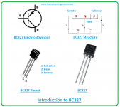
Yeah. Do go with the BC327. It can handle 800 mA and 625 mW vs 100 mA, 500 mW for the BC549. The two transistors have the same pinout. You do want the BC327 and not the BC337, though. The '337 is the PNP.
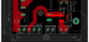
You can go with the minimum size annular ring on the two holes under the Mean Well, by the way. I'm not sure what those holes are for. Ventilation? Some sort of jig used by Mean Well during assembly? They're not for screws.
Tom
25 V electrolytic caps for 12 V is plenty. You could even use 16 V types if you wanted to.
Yeah. Do go with the BC327. It can handle 800 mA and 625 mW vs 100 mA, 500 mW for the BC549. The two transistors have the same pinout. You do want the BC327 and not the BC337, though. The '337 is the PNP.
You can go with the minimum size annular ring on the two holes under the Mean Well, by the way. I'm not sure what those holes are for. Ventilation? Some sort of jig used by Mean Well during assembly? They're not for screws.
Tom
Last edited:
They are vents, as Mark pointed out on the very first page. My original "self made" footprint indeed, had no provision for pads there (well, not even for drills, but that was a mistake 😛 ). Then, I learned that you can actually download footprints and 3D models from Mouser for almost any software, and thought that those would have "better" drill sizes, and pad sizes, etc. Upon replacing my own footprint with the one downloaded from Mouser, it added those pads around the vent holes.
I found it weird, but I kept it assuming they are done by someone that knows more than me.
I found it weird, but I kept it assuming they are done by someone that knows more than me.
You cheated, you edited the post after my reply and now it seems I am talking out of thin air about vents 🙂 .
Thanks for the other pointers, and yeah, it was the 327, sorry. OK, all good then. With those pointers, I should be able to create a BOM now.
As for point 1: copy-paste the traces from the top to bottom layer on the L, N and Chass traces? JPS's PCB seemed to go that route, Digikey's trace calculator for 10A seems to suggest 7mm traces, so duplicating them on both the top and bottom layer "kind" of gives that area on both traces. Seems reasonable. Any reason NOT to do it?
I found it weird, but I kept it assuming they are done by someone that knows more than me.
Yeah. I figured they were there for a reason as well, so I've made holes in my boards for them.
You cheated, you edited the post after my reply and now it seems I am talking out of thin air about vents 🙂 .
I'm sneaky like that. 🙂
As for point 1: copy-paste the traces from the top to bottom layer on the L, N and Chass traces?
I'm not sure what you'd accomplish with that.
You don't need 7 mm clearance between traces around the relay, so I would beef those connections up a bit so you get a stronger connection to the relay pins. You only need 2.5 mm between traces there (assuming 400 V peak, according to IPC2221B).
The 7 mm clearance is between any metal connected to chassis (PE) and either of the two wires connected to the mains (L, N). You also need 7 mm between the primary (mains) side and the secondary (12 V) side. That's for safety.
The minimum distance for two mains-connected traces should be set according to the voltage between the two traces.
Tom
Attachments
Yeah... Then connect Neutral to the ground terminal to fool those 3-prong electrical testers. ...
Why would they do that? (And most of this work was done before 3-lites were common.)
Once mounting the PCB in your enclosure don‘t forget to use spacer >= 10mm.
Tom, Rafa is talking about duplicating same traces L and N on both side for 2x 35um copper.
JP
Tom, Rafa is talking about duplicating same traces L and N on both side for 2x 35um copper.
JP
Makes sense the >10mm, but only after you pointed it out, so thanks!
How about those 2x traces JP? Was those on your PCB “intentional”, would you recommend them for my layout? Is there a downside os doubling up like that?
Thanks,
Rafa.
How about those 2x traces JP? Was those on your PCB “intentional”, would you recommend them for my layout? Is there a downside os doubling up like that?
Thanks,
Rafa.
BC337...NPN since ages. Why a BC337? Because even though BC549 is able to drive the relay apparently "lighter" transistors go defective prematurely.
Attachments

Last edited:
Friends, hopefully a quick question.
The Relay proposed by JPS is not available until September.
Do you think this is a viable replacement?
https://www.mouser.com/ProductDetail/TE-Connectivity-OEG/PCH-112L2M-WG?qs=rXmh1mW8ce1A9MwTuUzOIw==
Thanks!
Rafa.
The Relay proposed by JPS is not available until September.
Do you think this is a viable replacement?
https://www.mouser.com/ProductDetail/TE-Connectivity-OEG/PCH-112L2M-WG?qs=rXmh1mW8ce1A9MwTuUzOIw==
Thanks!
Rafa.
Or this other that apparently has the same footprint as the one previously suggested:
https://www.mouser.com/ProductDetail/TE-Connectivity/PCJ-112D3M303?qs=tub3WQyKOl8cLfi6spHMXA==
https://www.mouser.com/ProductDetail/TE-Connectivity/PCJ-112D3M303?qs=tub3WQyKOl8cLfi6spHMXA==
Why would they do that?
To "pass" a home inspection before a sale without having to upgrade the wiring. Connecting neutral to the PE terminal fools the 3-prong tester into thinking that the outlet is wired correctly. Obviously this is not safe or to code.
Once mounting the PCB in your enclosure don‘t forget to use spacer >= 10mm.
Yep. You then want 7 mm from the tip of the longest component lead to chassis, so a >10 mm spacer is appropriate.
Tom, Rafa is talking about duplicating same traces L and N on both side for 2x 35um copper.
Ah. I suppose if you can ensure that the current is shared evenly between top and bottom (and all the other constraints are met) that could be an option.
BC337...NPN since ages. Why a BC337?
My bad. Both BC327 and BC337 are NPNs.
One would have to check the data sheet, but I'd expect a 12 V power relay to draw around 50 mA. That's within spec for collector current of a BC549, but allowing for some VCE(sat) you quickly get close to the 100 mW limit of the BC549. The 625 mW of the BC327/337 will come in handy.
Do you think this is a viable replacement?
If you pound it in with a hammer... 😉 It looks like you've found one that'll fit the footprint, though. Good! Note that it's a 5 A relay. It sounds like you were designing for more.
Beware that relays are fickle creatures. They don't like having their pins bent. They don't like heat. They don't like moisture. They don't like flux. In fact, they'd much rather that you just leave them alone. This is mostly an issue for mass production, but do be a little careful when you unpack and solder the relay.
Tom
BC327 is since ages a PNP transistor just like BC337 is the NPN version 🙂 That is a second correction, sorry. Rafapolit needs the BC337.
The experiences with relays are scary. I haven't experienced this with good quality sealed relays like those produced by Schrack and in the past with classic Japanese brands like NAIS/Takamisawa etc. Of course plastic molded parts don't like heat and why one would bend the pins is unclear. "Open" relays are design error by choice. I never use cheap Chinese relays of any kind. For power/current switching: when possible choose fully sealed types with low holding current, bifurcated AgNi contacts and choose higher current ratings than strictly necessary.
In 2016 I replaced a large quantity of 1979 built lighting relays of dutch quality that had been in 12/7 service since then (and were overloaded for a long time as well) and only now started to have problems.
I notice a trend in the dislike of older heavy or mechanical parts like relays, transformers and real mains power switches but be assured that their replacements have a shorter service life. It is disappointing that the older parts were of much better quality than more recent ones but that counts in more areas.
Attachments
Last edited:
Well, not really. Since I am noob, I was mostly copying Mark Johnson's implementation of his soft-start system. So, it had a 16A/12A relay.... It looks like you've found one that'll fit the footprint, though. Good! Note that it's a 5 A relay. It sounds like you were designing for more...
Once JPS suggested the smaller relay, I commented that, if I need 10A or more, probably better to go with Mark's implementation and include the soft start. And I am happy to have mine for smaller PREs and HPAs that typically draw about 500mA. So I thought 5A would be enough, even considering inrush current.
Is this reasoning sound? Or do I you think I still need a more beefy relay?
Thanks,
Rafa.
Well, I meant circuit-wise. I will have to adapt the PCB, that is the beauty of still having a non-finalized design. If that one is a bit better, I could change the PCB layout. But yeah, something that fits more than one solution is probably a better alternative....If you pound it in with a hammer... 😉
Thanks jean-paul! And if I can abuse your helping hand, how do I determine if I require the 16, the 25 or the 40 version? Is there a way to know / simulate / guess, before hand, or do I need to test it in circuit and see which hFE values I require?...Rafapolit needs the BC337...
Thanks once more,
Rafa.
Eidt: about september, yes, I'm compiling the BOM listing availability to see how they will change once I have finished the process 🙂
You can just choose the -40 version as there is no such thing as too high hFE here.
Last edited:
BC327 is since ages a PNP transistor just like BC337 is the NPN version 🙂 That is a second correction, sorry.
No worries. If I'm wrong it's entirely fair to correct me. Or is there a limit on the number of corrections I'm allowed? Sorta like a three-strikes rule?
I can't decide whether I should blame inattention (i.e., looking but not seeing), old age (my birthday is next week), sleep deprivation, or working too hard for too long. 🙂
Thanks for setting me straight. It's rather important to get the NPN if the circuit is supposed to work.
Tom
- Home
- Amplifiers
- Power Supplies
- PCB: Push on / Push off Mains Switch