Have you considered a slot port? Easy enough to get almost any length even if depth of the box is limited
Yes I'd like that then I could put it on the back or front, what size should it be, the slot space would need to be 288 mm wide. For the 46.71 litre size.
Regards Tim
Last edited:
Actually those measurements would make it too narrow, this is what I came up with. 1.2" height x 5" wide x 3.66" long. I think I'll put it on the back. Does it check out?

Last edited:
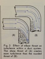
Great analogy for the mechanics but air will not behave like a ball on a string in a tube...The best analogy I can think of ...
Mass is reactive but turbulence isn't. What you've shown here is a one directional duct.Because air has mass and moving mass doesn't want to change directions, air moving in a bent duct most certainly does suffer turbulence.
As I already said, port tuning is not my strong suit so please correct me if I'm wrong. I think the port length equation is:Yes I'd like that then I could put it on the back or front, what size should it be, the slot space would need to be 288 mm wide. For the 46.71 litre size.
Port Length (L) = (2.35625 × 10^4 × D^2 × N) / (Vb × Fb^2) - K × D
Where:
D - Diameter of vent
N - Number of ports
Vb - Volume of box
Fb - Tuning Frequency
K - End correction factor
L - Vent or Port Length
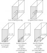
And end corrections factors according to attached image.N - Number of ports
Vb - Volume of box
Fb - Tuning Frequency
K - End correction factor
L - Vent or Port Length
I further think that you are supposed to keep the height to width ratio of a slot port no more than 1 to 8.
288 mm wide -> 36 mm height. 28.8 x 3.6 = 103.68 cm2 -> 11.49 cm diameter of a circular port.
Fb = 25.1 Hz for the woofer if Vb = 54.5.
K = 2.227 for a slot port.
Port Length (L) = (2.35625 × 10^4 × 11.49^2 × 1) / (54.5 × 25.1^2) - 2.227 × 11.49
L = 65 cm, that is a rather long port...
If you don't care about the 1:8 ratio (seems to be based on some JL Audio whitepaper without any reason or data for why they recommend 1:8 as the maximum ratio) and make the height of the slot port 2 cm instead.
28.8 x 2 = 57.6 cm2 -> 8.56 cm diameter of a circular port.
Port Length (L) = (2.35625 × 10^4 × 8.56^2 × 1) / (54.5 × 25.1^2) - 2.227 × 8.56
L = 31.2 cm.
Attachments
Last edited:
Emu, could it be you have not loaded your x/o sim in VCad with real drivers .frd and .zma files?
The problem is that the mass is made up of individual molecules of air that naturally behave like individual tiny masses. The air molecules don't know any different about AC or DC, their behaviour is determined physics. When the direction reverses, the turbulence of course occurs at the other side of the bend. It's generally accepted to keep air velocities in ports to less than 17 meters per second, or at 28Hz ~0.3 meters of air flow each direction per cycle.Mass is reactive but turbulence isn't. What you've shown here is a one directional duct.
The effective mass of the air in the port tube is oscillating on the effective compliance of the air in the cabinet plus driver. Irrespective of whether the mass is air in a tube on the springiness of the speaker driver and cabinet, or a ball of the same mass on an elastic string of the same spring compliance, the resonant frequency of the mass is determined by Hooks Law. The paddle and ball analogy is a valid visualisation of what happens in an ideal bass reflex tuning port.Great analogy for the mechanics but air will not behave like a ball on a string in a tube...
Port Length (L) = (2.35625 × 10^4 × 8.56^2 × 1) / (54.5 × 25.1^2) - 2.227 × 8.56
L = 31.2 cm.
Thankyou, I'd read another forum member saying he used a narrow square port and it induced a whistling sound.
I checked out your round port sizes on 4 or 5 different online calculators last night and it checks out to be accurate.
I guess whistling sound could be a problem if the slot gets too narrow but air velocity is probably part of the problem. A 28.8 x 2 cm slot port represents a slightly larger area than a 3 inch round port. But why not get a bit creative with it? The major problem with this slot port is the width, right? So why not make it more narrow and it can then be of proper height (and also be tuned to a suitable length).Thankyou, I'd read another forum member saying he used a narrow square port and it induced a whistling sound.
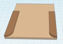
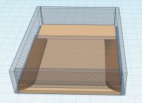
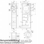
Look at the two attached images. I have tried to illustrate the bottom of the box in light brown and two pieces of MDF on top of it in darker brown. Those two pieces can be made to adjust height and width of the port then cut to length. I have rounded them to make a flair. The second image is me trying to illustrate how the rest might go around the bottom to make up the slot port.
Note: Troels uses a 20 x 200 mm slot port in his ScanSpeak Bookshelf-3WC build. He uses aperiodic tuning for that build but I don't think a 20 mm slot port necessary being too narrow: Bookshelf-3WC
Attachments
Last edited:
The slot space would need to be 288 mm wide. For the 46.71 litre size.
Regards Tim
That looks very nice I like it but I think you did the calcs based on 54.5 litres not the 46.7 figure you also gave me earlier, last night I tried to get 54.5 litres but just didn't have the space in it, 46.7 gives me lots of room for bracing and the the slotted port wall thickness.
The online calc I used says I only need 7.26" long slotted port length with those dimensions. I couldn't work out why such a difference with the same dimensions. I think this one is inaccurate see screenshot.
Port Length Calculator

OK. I will do all simulations from now on based on 46.7 liters for the woofer.That looks very nice I like it but I think you did the calcs based on 54.5 litres not the 46.7 figure you also gave me earlier, last night I tried to get 54.5 litres but just didn't have the space in it, 46.7 gives me lots of room for bracing and the the slotted port wall thickness.
K = 2.227 for a slotted port will make it shorter. The reason behind the 2.227 constant is quite complex and it looks like a lot of online converters (and even simulation software) only do conversion based on port area.The online calc I used says I only need 7.26" long slotted port length with those dimensions. I couldn't work out why such a difference with the same dimensions. I think this one is inaccurate see screenshot.
VituixCAD is giving me Lv = 27 cm for Vb = 46.7 liters, a 57.6 cm2 port (288 x 20 mm) and K = 2.227 (but you have to enter K = 2.227 manually because it is using 0.850, two flanged ends by default). You can also se that the area represents a circular port with a diameter of 8.6 cm:
Code:
STATISTICS
 f3     34.6 Hz
 f6     28.7 Hz
 f10    23.8 Hz
 Zmin    6.8 Ohm @ 39793.9 Hz
 Zmax   24.6 Ohm @ 13.2 Hz
 GDmax  14.7 ms  @ 24.5 Hz
 XmaxC   4.5 mm  @ 5 Hz
 VmaxR   1.9 m/s @ 21.2 Hz
 Pmax    1.2 VA  @ 39793.9 Hz
-------------------------------------------------------------
DRIVER: Dayton Audio RS270P-8A, 1 pcs in series
 n0      0.31 %       Reference efficiency
 SPL     87.0 dB/W    Sensitivity
 USPL    87.7 dB/2.83 Sensitivity
 EBP     54.5         Efficiency bandwidth product
 Dd      21.0 cm      Effective diameter of driver
 Vd     207.8 cm^3    Maximum linear volume of displacement
 Cas  7.92E-7 m^5/N   Acoustic equivalent of Cms
 Mas    6.1E1 kg/m^4  Acoustic equivalent of Mms+Mme
 Ras   6.75E3 Ns/m^5  Acoustic equivalent of Rms
 Rae   2.07E4 Ns/m^5  Acoustic equivalent of Re+Rg
-------------------------------------------------------------
BOX REAR 1: Vb=46.7 l, Ql=7.0
 Fb      28.3 Hz      System resonance frequency
 Cab   3.3E-7 m^5/N   Acoustic compliance of air in enclosure
 Rab   5.66E2 Ns/m^5  Acoustic resistance due to absorption
 Ral   1.19E5 Ns/m^5  Acoustic resistance due to leakage
-------------------------------------------------------------
VENT REAR 1: Dv=8.6 cm, Lv=27.0 cm
 Sp      57.6 cm^2    Effective area of port
 Map   9.54E1 kg/m^4  Acoustic mass of air in port
Rap 1.7E2 Ns/m^5 Acoustic resistance of port lossesOk thanks
I like what you did in the detail in the attachment, is this viable in attachment here with a 36mm high slot if not then a 25mm slot. For 46.71 litre? I would do it front facing as it looks nice.
Regards Tim

I like what you did in the detail in the attachment, is this viable in attachment here with a 36mm high slot if not then a 25mm slot. For 46.71 litre? I would do it front facing as it looks nice.
Regards Tim
So the hole I see in the picture is at the back and the port flare is facing forward, right?Ok thanks
I like what you did in the detail in the attachment, is this viable in attachment here with a 36mm high slot if not then a 25mm slot. For 46.71 litre? I would do it front facing as it looks nice.
175 x 36 mm equals a port area of 63 cm2 -> 30.4 cm port length.
Code:
VENT REAR 1: Dv=9.0 cm, Lv=30.4 cm
 Sp      63.0 cm^2    Effective area of port
Code:
VENT REAR 1: Dv=7.5 cm, Lv=18.4 cm
Sp 43.8 cm^2 Effective area of port[RANT-WARNING-BEGIN]
Here is my problem with a ported design in general. Is the 2.227 end correction factor true for a slot port? I have tried to trace the origin of that "German picture" but I come up short. I can find all kinds of traces of it all over the net, just like I can find all kinds of ideas about different end correction factors. Different online calculators and simulation software give different answers feeding them the same data. Now add empiric measurements like the ones Troels done and the ports seems to deviate even from the most commonly accepted algorithms. Then there is the way JL Audio seems to derive the end correction factor. To me this seems to be more guesswork than science.
[RANT-WARNING-END]
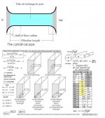
With that being said, look at the attached image. Its a bit more than just the images of the different end correction factors (supposedly empirically derived). I will try to follow up the links and the calculus on that image whenever I get some spare time. But whats important is the way the flare is supposed to be accounted for when calculating the port length. I assume the "half flare" distance is applicable to a circular port but how does it apply to a slot port? I have no idea, especially if its on only two sides of a slotted port. So take this for what it is, qualified guesswork at best. Your 53 mm radius flare cover 5 cm (if height of slot = 25 mm) of the total slot port perimeter of 40 cm. If 100% of the circumference of a circular port equals 50% of the length would 12.5% of the perimeter of a slot port equal 93.75% of the flair length? If that would be the case then you have to multiply the slot length with 1.125 to get the total length (including the flare). The length for a 25 mm slot height is then: 18.4 x 1.125 = 20.7 cm...
Ps. I tried to follow the link to Linear Team's port calculator but its broken. Seems like it could be this one though: Port Length Calculator
I entered the values for a slot port of 175 x 25 mm, a box volume of 46.7 liters and a tuning frequency of 28.3 Hz (the values I got from VituixCAD). The result I got back from the online calculator was: 8.24 inch = 20.93 cm.
Attachments

Last edited:
So the hole I see in the picture is at the back and the port flare is facing forward, right?
The hole is the front of the speakers I just drew it like that because it was easier. The flare will be forward facing at the bottom of the speakers.
The pieces that sandwiches the flares between them will need to extend past the flares at the front 6mm so I can radius the edges a little for a smooth exit. I think that may change the port volume a little.
I did the calculations with that link and got the same 8.25" length. I like this, I think it will suit my box. I saved the photo too thanks ☺️
Regards Tim
Last edited:
For reference and future documentation, I think I found the text that goes with the "German picture" of end correction factors (see quoted text below and attached file). So this adds a bit of context to the picture. A quick highlight from the text translated to English:
The following applies to the correction factor:
Ps. Note: the author is comparing the formula Lv = 10 * c ^ 2 / (16 * pi) * D ^ 2 * Np / (fb ^ 2 * Vb) -k * D, to F.H's formula l = 10 x c² x A / 4 x pi² x fb² x Vb - (0.5 x (Pi x A) ^ 0.5). The former using different end correction factors where the latter seems to use a general end correction factor of about 0.785.
The following applies to the correction factor:
- 0.85 for port flush on both sides (e.g. housing wall only)
- 0.732 for one-sided flush ports (normal case)
- 0.614 for ports protruding on both sides inside and outside (e.g. with a screwed-in pipe, if the flange is not countersunk)
- 2.227 for a port like the VOX 25x
- 1.23 for a three-sided enclosed port that only has one extending side wall (see VISATON 'Filou')
- 1.728 for a port extended by two housing walls.
Ps. Note: the author is comparing the formula Lv = 10 * c ^ 2 / (16 * pi) * D ^ 2 * Np / (fb ^ 2 * Vb) -k * D, to F.H's formula l = 10 x c² x A / 4 x pi² x fb² x Vb - (0.5 x (Pi x A) ^ 0.5). The former using different end correction factors where the latter seems to use a general end correction factor of about 0.785.
Hallo,
ob die erwähnten Korrekturfaktoren zu F.Hs Formel passen denke ich nicht! Diese Formel lag meinen Berechnungen jedenfalls so nicht zugrunde und enthält per se auch keinen solchen Faktor. (er ist dort pauschal mit 0,5 x pi x F gesetzt) Wenn ich mich also diesbezüglich einmal selber zitieren darf:
Die (von mir verwendete) Formel zur Berechnung des Mindestdurchmessers des BR-Tunnels ist:
r=((0,008838*Wa^0,5)/(fb*mach))^0,5
mit
r = Tunnelradius
Wa = maximal abgestrahlte Schallenergie in akustischen Watt
mach = maximal zulässige Strömungsgeschwindigkeit in Mach-Einheiten
Wa = (9,52*10^-7*fs^3*Vas*We)/Qesn
mit
We = maximale elektrische Eingangsleistung in Watt
Qesn = Qes unter Einbeziehung von Serienwiderständen wie Kabel, Spule im Tiefpass etc.
Qesn = ((Re+Rx)/Re)*Qes
mit
Re = Gleichstromwiderstand des Chassis
Rx = Summe aller Serienwiderstände
So, nun haben wir den Mindestradius ermittelt, fehlt noch die Länge:
Lv = 10*c^2/(16*pi)*D^2*Np/(fb^2*Vb)-k*D
mit
c = Schallgeschwindigkeit ca. 344m/s
D=Rohrdurchmesser in cm
NP=Anzahl Rohre
k = Korrekturfaktor
Für den Korrekturfaktor gilt:
0,85 für Tunnel beidseitig bündig (z.B. nur Gehäusewand)
0,732 für einseitig bündige Tunnel (Normalfall)
0,614 für beidseitig innen wie außen überstehende Tunnel (z.B. bei eingeschraubtem Rohr, wenn der Flansch nicht versenkt wird)
2,227 für einen Tunnel wie bei der VOX 25x
1,23 für einen dreiseitig umschlossenen Tunnel, der nur eine verlängernde Seitenwand hat (siehe VISATON 'Filou')
1,728 für einen von zwei Gehäusewänden verlängerten Tunnel.
Negative Länge kommen z.B. bei zu geringen Querschnitten und/oder hohen Abstimmungen gerne mal vor, also wenn ein normales Rohr schon nicht sehr lang wäre.
Generell kann man sagen: Wenn das normale Rohr schon nicht länger ist als k*D (Korrekturfaktor mal Querschnitt) dann werden die Ergebnisse zwangsweise negativ.
Nehmen wir mal folgendes an:
Durchmesser 10cm, Länge bei einseitig bündigem Rohr ebenfalls 10cm; k=0,732
Dann heißt das nichts anderes als das das unverkürzte Rohr 10 + 0,732 * 10 lang wäre, denn 0,732 * 10 wird ja in der Berechnungsformel am Schluß als Korrektur abgezogen.
Dabei kommt 17,32 heraus.
Umgewandelt in einen VOX-Kanal identischer Fläche mit k=2,227 ergibt das aber nun 17,32 - 2,227 * 10, also 17,32 - 22,27, was eindeutig ein negatives Ergebnis bringt.
Bei Reflexrohren mit Trompetenöffnungen gibt es auch wieder mehrere Korrekturfaktoren:
für die
- einseitig bündige Einfachtrompete
- einseitig bündige Doppeltrompete
- das Ganze mit verschiedenen Krümmungsradien...
- beidseitig bündige Doppeltrompete
Dazu sei hier erst mal so viel gesagt, dass trompetenförmige Öffnungen den k-Faktor drastisch reduzieren, d.h. er liegt für freistehende Rohre um 0,6 oder sogar noch darunter. (Das hängt u.a. auch vom Krümmungsradius der Öffnungswölbung ab.)
So, zu guter letzt der Vergleich mit F.Hs Formel:
Es steht zu lesen:
l = 10 x c² x A / 4 x pi² x fb² x Vb - (0,5 x (Pi x A)^0,5)
wobei
l = Länge des Tunnels in cm
c = Schallgeschwindigkeit in Luft (343 m/s)
A = Querschnittsfläche der Tunnelöffnung in cm² (bei mehreren Öffnungen die Summe der Flächen)
fb = Tuningfrequenz der Box
Vb = Nettovolumen der Box in l
Die von mir verwendete Formel unterscheidet sich nur auf den ersten Blick, entspricht aber bis zum Minus-Zeichen exakt derjenigen von F.H.
(Ich verwende anstelle der Gesamtrohrfläche das Produkt aus Rohrdurchmesser und Rohranzahl, aufgelöst sieht das dann so aus:
F.H. l=(10 x c² x A)/(4 x pi² x fb² x Vb)
wobei in A der Faktor NP für die Anzahl der Rohre je bereits enthalten ist, woraus dann folgt:
l=(10 x c² x 2 x pi x r x NP)/(4 x pi² x fb² x Vb)
Da kürzt sich pi einmal heraus, was uns zu
l=(10 x c² x 2 x r x NP)/(4 x pi x fb² x Vb) führt, was widerum zusammengefaßt in
l=(10 x c² x D x NP)/(4 x pi² x fb² x Vb) mündet.
Das ist die von mir verwendete Formel bis zum Minuszeichen.
Der einzige Unterschied besteht nun im Rest nach dem Minuszeichen:
Korrekturfaktor bei F.H. ist pauschal 0,5 x Wurzel(pi x A), bei meiner Berechnung lediglich D*k mit variablem k.
Der Pauschalfaktor von F.H. entspricht einem k von etwa 0,785 und liegt damit sehr nah beim Wert für ein einseitig bündiges Rohr.
Eine absolut akzeptable Näherung wenn man einmal bedenkt, dass genau diese Bauform die häufigste ist. (Die Abweichung liegt regelmäßig um 0,5cm, bei kleineren Rohrradien darunter, was in der Tat fast völlig vernachlässigbar ist.)
Es wird jedoch deutlich, dass auch die Formel nach F.H. bereits einen Korrekturfaktor enthält! Die Anwendung eines weiteren Korrekturfaktors auf die Ergebnisse der Berechnungen nach F.H. würde demnach zu falschen Ergebnissen führen...
Meine Berechnungsweise schließt jedoch die Festlegung des Rohrdurchmessers und damit der Querschnittsfläche des BR-Kanals ein. Hier zeigten ebenfalls) empirische Versuche, dass Strömungsgeschwindigkeiten zwischen Mach 0,05 und Mach 0,1, typischerweise Mach 0,75 günstig sind.
Größere Durchmesser führen hierbei zu niedrigeren Strömungsgeschwindigkeiten. Allerdings zeigen Simulationen, deren Berechnungsvorschriften hier allerdings aufgrund ihrer Komplexität unmöglich wiederzugeben sind, dass mit zunehmendem Rohrdurchmesser die Stärke der Rohrresonanzen drastisch zunimmt. Die Forderung muß also sein: So groß wie nötig und so klein wie möglich.
Hierbei spielt ebenfalls die maximale Eingangsleistung eine Rolle. Man sollte sich fragen, ob es tatsächlich sinnvoll ist, die maximale Verstärkerleistung hier in Ansatz zu bringen. Das führt nur dazu, dass der Rohrquerschnitt groß und damit das Rohr lang wird, wobei dadurch Strömungsgeräusche in Lautstärkebereichen vermieden werden, die unrealistisch für die Mehrzahl aller Hörsitzungen sind. Dafür handelt man sich u.U. auch bei niedrigen Eingangsleistungen gut hörbare Rohrresonanzen ein, die zu Verfärbungen im Klangbild führen.
Hierzu existiert ein alter Trick, der aber dennoch wirksam ist. Er dient dazu, die Rohrresonanz zu entschärfen.
Und so funktioniert's:
1. Man berechnet die BR-Box ganz normal.
2. Jetzt wird fb mit 0,707 (1/Wurzel 2) multipliziert.
3. Anhand der neuen fb bei gleichbleibendem Vb (!) berechnet man die Rohrlänge nun neu.
4. Das neue Rohr wird exakt auf halber Länge rundum mit einem kleinen Bohrer durchlöchert, 8-12 Bohrungen je nach Durchmesser entlang des Umfanges reichen aus.
Wer hat's ausgedacht und getestet?
elrad im Jahre 1986
Was steckt dahinter?
Geht eine beidseitig offene Röhre in Resonanz, dann befindet sich an jedem der Enden jeweils ein Schallschnellemaximum und in der Mitte ein Schalldruckmaximum. Wird nun genau in der Mitte der Druckaufbau unterbunden, dann können die einzelnen Maxima logischerweise nicht mehr entstehen. Ergo kann auch die unerwünschte Resonanz nun nicht mehr auftreten. Genau das wird mit dem Aufbohren des Tunnels bewirkt.
Funktioniert das auch?
Ja.
Die hatten es damals mit dem Bauvorschlag der Vifa 'Korrekt' gemacht, den ich aufgebaut habe, und darin hat es funktioniert.
Nachteile?
Nun, das Rohr wird erheblich viel länger, was angesichts der heute üblichen Bauvorschläge zumeist kaum noch realisierbar ist. Außerdem entsteht eine neue Resonanz aufgrund der nunmehr halben Rohrlänge, die aber schwächer ausgeprägt ist.
So, spätestens jetzt sollte es hier niemanden mehr geben, der Probleme mit Baßreflexrohren/kanälen/tunneln/schächten/wasauchimmer hat.
mfg
Tomtom
Attachments
Last edited:
I think it best I use the info provided re the crossover and source a ready made crossover.
I tried incorporating the port slot in my box today and it was too difficult due to the fact I have already assembled the sides and front. I'll put a round port in the side.
I was thinking of buying this Dayton signal processer DSP-408 to fine tune my new set up?
Dayton Audio - DSP-408 4x8 DSP Digital Signal Processor for Home and Car Audio
It could be enjoyable to use it but I'd need some help. Although I'm not sure there would be much benefit? My set up is new and a little different from the norm so it may prove to be of benefit ? What do you think?
Regards Tim
Last edited:
That is a rather big question, here is my quick answer...What do you think?
I have no experience of the Dayton Audio - DSP-408 4x8 DSP but I personally really like using a DSP in general. They can be super powerful and flexible if used correctly but I guess they would be equally powerful butchering the sound quality if used incorrectly. IMHO, the only way to truly harness the power of a DSP are a lot of knowledge and careful measurements. An understanding of the problems at hand, an idea how to use the DSP to solve them, or at least part of the equation. Skills to set it up right and to measure the result. Perseverance to do it over and over again to finally get it right. You can off course play around with it by ear until you find it sound good enough but its a bit like building a speaker entirely on manufacturer specifications and simulations. The result might be decent but not as good as it could have been, sometimes even far from it. Building without measuring is like flying blind. Its the same with the DSP, programming without measuring would to me be wasteful.
With that being said, lets take a quick look at your use-case. You can use the DSP as one of the crossovers, I would pick LF since those components are the most expensive. But it will also enable you to extend bass with EQ, e.g. using a Linkwitz transform (only if you got a sealed design). I would personally (as I said before) go for a sealed design and EQ it down to around 30 Hz. Know that the DSP works on line level so you will have to have a preamp for source selection, volume control etc. and two separate power amps (one for LF and one for HF). You will also have to go semi-active for a 3-way, so you go with a passive filter between mid and tweeter and use the DSP as the crossover between woofer and mid. Also note that you might need a lot of power if you are going to extend bass with a 10 inch woofer, keep it sane and do the math before you commit to it.
Last edited:
One of my concerns I didn't consider before purchasing the Dayton 10" woofer was that almost all my vocals will be coming from it. I'll have to crossover higher than 400 Hz with a ready made crossover probably 700hz.
I'm not sure but it seems to me a 6.5" or 5" mid woofer would be a better instrument for doing this.
Would the vocals sound better in a sealed enclosure using my 10" woofers than in the ported enclosure I was planning?
If so I would prefer to use a sealed enclosure instead with it. My only other question would be I'd have way more volume for my sealed 10" woofer than I need, is there a way the I could use the space I have for a better result with sealed enclosure?
Regards Tim
Last edited:
- Home
- Loudspeakers
- Multi-Way
- New Crossovers with Hz/db switches & DIY speakers