As promised, I wasn't going to just build this amp and call it good. That's not my style 🙂
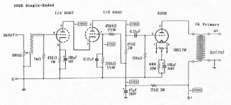
I agree now this JC Morrison circuit has issues. Possibly if you only need a couple of watts and have a very low level source it would be a "final design" but after some listening/testing I did a complete rework of the driver circuit. I swapped it to a cascoded 6SN7, with a voltage divided upper grid, as seen in the updated schematic I drew up.
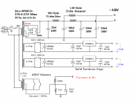
This greatly improved the bass response, calmed down the brightness, got rid of the early asymmetrical clipping and traded some input sensitivity for 3X the power output at reasonable distortion levels. It still hits full power with a 1.1V RMS input signal and sounds really good now with my EAR 834 phono stage or my Yamaha CD deck. I did a slight change to the PSU, to raise the DC offset of the 6SN7 filaments to 50V, to split the diff as one cathode is now running at 100V.
I'm not done, but this topology change has the project clearly headed in the right direction. Might try tweaking some voltages, changing a few caps and still want to play around with a LED + resistor on the lower section of the cascode. Also have done a bit of tube rolling to get something, that for a lower cost 300B, sounds quite good.
I believe there is more here to be had, so stay tuned!
Tuning and modifying a JC Morrison style 300B DIY tube amp. - YouTube
I agree now this JC Morrison circuit has issues. Possibly if you only need a couple of watts and have a very low level source it would be a "final design" but after some listening/testing I did a complete rework of the driver circuit. I swapped it to a cascoded 6SN7, with a voltage divided upper grid, as seen in the updated schematic I drew up.
This greatly improved the bass response, calmed down the brightness, got rid of the early asymmetrical clipping and traded some input sensitivity for 3X the power output at reasonable distortion levels. It still hits full power with a 1.1V RMS input signal and sounds really good now with my EAR 834 phono stage or my Yamaha CD deck. I did a slight change to the PSU, to raise the DC offset of the 6SN7 filaments to 50V, to split the diff as one cathode is now running at 100V.
I'm not done, but this topology change has the project clearly headed in the right direction. Might try tweaking some voltages, changing a few caps and still want to play around with a LED + resistor on the lower section of the cascode. Also have done a bit of tube rolling to get something, that for a lower cost 300B, sounds quite good.
I believe there is more here to be had, so stay tuned!
Tuning and modifying a JC Morrison style 300B DIY tube amp. - YouTube
Attachments
Yes, exactly. It's simple, low cost and should sound good. The big advantage is that many commercial amps use this circuit, including Chinese ones. I have a friend that is setting up exactly this circuit and he's finding it very useful.
I'm the first to admit: I am pretty shocked that a schematic this widely used, and praised by some, is this bad lol. I posted to this thread my findings, did a video of my redesign, and am baffled by some of the articles I have seen based on this design.
Good luck with redesigning the circuit! My solution is a plate choke, FT-2 teflon coupling cap, and a triode with a mu of 30 or a bit more. Still well within "budget' since Russian caps are good value on eBay, and you could use a Hammond 156C or 157G (as in the Hagerman Tuba).
Good luck with redesigning the circuit! My solution is a plate choke, FT-2 teflon coupling cap, and a triode with a mu of 30 or a bit more. Still well within "budget' since Russian caps are good value on eBay, and you could use a Hammond 156C or 157G (as in the Hagerman Tuba).
Any suggestion of a good octal triode to try? I've had good luck using a 6SQ7 on another amp but it has a lot higher MU than you are sugesting.
Mu itself isn't so important for cascodes, because the stage's gain is much more like a pentode, Gm times load impedance. The really tricky bit is swinging 100 Volts peak-to-peak linearly enough to not embarrass a 300B. Definitely not trivial with a B+ derived from the 300B's supply. More B+ is more better, in every way.
All good fortune,
Chris
All good fortune,
Chris
Mu itself isn't so important for cascodes, because the stage's gain is much more like a pentode, Gm times load impedance. The really tricky bit is swinging 100 Volts peak-to-peak linearly enough to not embarrass a 300B. Definitely not trivial with a B+ derived from the 300B's supply. More B+ is more better, in every way. All good fortune,
Chris
With a 2 stage topology more B+ is better for a resistor (more current) or some combination of 2 tubes. When you don't have that a plate choke solves a lot of issues. Ideally a nice amorphous one, but on a budget even the cheap Hammonds work - I've used both 156C and 157G. In octal one option is using the two halves of a 6SL7 in parallel, but I haven't tried that. I've seen it on some schematics. Stated dissipation is 1 watt, so you could get some current through it even using one half. With a Ri of 44K this suggests two 156C in series as plate chokes. I and others have used 2 in series in the past and got decent results. There's the suggestion of using them bottom to bottom and out of phase to act as a humbucker if you do a search. Here's an example with a 26. Post #913. Since they're unscreened in any way, proximity to existing transformers and chokes could be an issue. When I used them I put the PSU in another chassis. No free lunch here.
https://www.diyaudio.com/forums/tubes-valves/151421-26-pre-amp-92.html#post2512539
.
Last edited:
With regard to the 6SL7 stated dissipation is 1 watt, so you could in theory get some current through it even using one half. The suggested current in the data is 2.3mA but there's no maximum stated. 6mA for one half would be nice and within dissipation limit at a lower anode voltage, but I've not seen that tried and I've no idea if it would stress the tube too much. If you used both halves I imagine 6mA is achievable and you'd start to get some drive. How it sounds I have no idea.
1. The cascode 6SN7 circuit in Post #41 avoided a potential problem that the earlier Posts # 6 and #25 cascade circuit could have.
2. Earlier posted cascade circuit:
Just be sure to use a short low capacitance cable from the 100k pot wiper to the grid of the 6SN7.
It is not likely to be an issue, but here comes an extreme example:
Diagonal across a 1.4 foot chassis is 2 feet, and high capacitance RG58 will have 60pF of capacitance.
If the 6SN7 in circuit has a gain of 15, the 4pf plate to grid capacitance will have 60pF of Miller Effect Capacitance.
If the signal source output impedance is 0 Ohms, then the -6dB setting of the volume pot is 50k at the wiper.
50k and 60pF + 60pf (120pF) is already -1 dB @ 13.3kHz, and we already have that much high frequency rolloff at the first 6SN7 grid.
3. Post # 41, with 60pF of coax capacitance, and the very low Miller Capacitance of the first grid of the 6SN7, we are ~ -1dB @ 26.6kHz at the first grid of the 6SN7. And, the next high frequency roll off problem using the cascode circuit is the high plate impedance of the cascode output.
There, we have 27k RL driving ~ 60pF of the 300B Miller effect capacitance. 27k and 60 pF is ~ -1dB @ 49 kHz, much better.
As long as we can linearly drive +/- the 300B bias voltage, we are OK.
4. I always think it is interesting how easily we can roll off the high frequencies.
Last edited:
With proper design care, a single [Octal] 6SL7 can be paralleled.
Individual self bias resistors.
Individual self bias bypass caps.
Individual grid stopper resistors.
Parallel the plates.
Done
You get:
rp reduced by 2
Gm doubled
Current doubled
The same mu (u)
Double the capacitances
For those who do not like parallel tubes, please analyze the following:
1. A real 2A3 with 2 filaments, 2 grids, and 2 plates.
2. A 300B that has slightly different dimensions from one side to the other:
filament to grid to plate on one side.
filament to grid to plate on the other side.
Parallel tubes indeed, you are already listening to them, and you did not even realize it!
IRMC
Last edited:
For those who are not afraid of solid state in a vacuum tube circuit,
an IXYS 900V part makes a very good current source load for many tubes plate resistance, rp.
The IXYS current source does require more B+ than a choke plate load.
But it is lighter, less expensive, and does not pick up hum.
I use that IXYS part for my parallel 12AY7 triodes in single ended amplifiers, including 300B that only have about 60V filament self bias.
Last edited:
Tony,
I bet it sounds great!
It looks very nice.
When you get the chance, would you please draw up and post your schematic?
Or if you would please, just answer a few questions:
Is the EL84 in Pentode or Triode mode?
Is the EL84 plate load a resistor or a current source?
Is the EL84 to 300B RC coupled, or DC coupled?
What is the output transformer primary impedance?
No negative feedback, correct?
Is it Rainy or Dry season there now?
I do not know if I will ever return to the Philippines to see it again.
Tony,
I bet it sounds great!
It looks very nice.
When you get the chance, would you please draw up and post your schematic?
Or if you would please, just answer a few questions:
Is the EL84 in Pentode or Triode mode?
Is the EL84 plate load a resistor or a current source?
Is the EL84 to 300B RC coupled, or DC coupled?
What is the output transformer primary impedance?
No negative feedback, correct?
Is it Rainy or Dry season there now?
I do not know if I will ever return to the Philippines to see it again.
el84 is the best sounding pentode i ever heard, along with the 6v6, i run it pentode..
i used a plate load resistor on the el84, target current is about 20ma at 250 volts plate..
rc coupling, using 0.33ufd/1200vdc WIMA mkp caps..
output traffo is 3.5k to 8 ohm speaker....
no global feedback...
Last edited:
el84 is the best sounding pentode i ever heard, along with the 6v6, i run it pentode..
i used a plate load resistor on the el84, target current is about 20ma at 250 volts plate..
rc coupling, using 0.33ufd/1200vdc WIMA mkp caps..
output traffo is 3.5k to 8 ohm speaker....
no global feedback...
I can also confirm that EL84 run in pentode mode is the best sounding driver I have tried so far with my 300B amps (and I have tried a number of them).
Operating parameters are as following: anode load 12KΩ, plate voltage 270 V, screen voltage 160 V, cathode current ca. 12 mA.
My future plans include trying the EL84 in triode mode and 6J9P-E also in triode mode with a choke load (I have used the latter in another experimental amp and I was very impressed of it)
Just picking up on the parallel 6SL7 idea - the Sylvania data sheet states the absolute maximum current per triode is 3.2v. So 3mA per section may work, giving a total of 6mA. Rp would be around 22K. With 160v anode-cathode, dissipation per section would be 0.5W which is only half of the maximum 1W. Should work with an active load or high inductance choke.
I can also confirm that EL84 run in pentode mode is the best sounding driver I have tried so far with my 300B amps
Yes, pentode driver is good, and it's usually easy to move on from 6SN7 cascode (that Stephe described recently) to a pentode, and get allround improvement in sound.
The pentode G2 supply is easily provided by a simple resistor divider, and a DC-Link capacitor 22-50µF .
Modern all-glass 9-pin types are best: EL84 is good, but I like 6BW7 slightly better. This may be because running at Va=250-300V, Vg2=150V, Ia=10-12mA is nearer to the data-sheet most-linear operating point for 6BW7 and a number of other similar pentodes, compared to the usual 40-50mA for power pentodes like EL84. But still, the EL84 gives good sound.
With proper design care, a single [Octal] 6SL7 can be paralleled.
Individual self bias resistors.
Individual self bias bypass caps.
Individual grid stopper resistors.
Parallel the plates.
Done
I have a pair of 6SL7 tubes. I might give wiring them up like this a try at some point.
I did change the cathode bias on the lower section to a cheap red LED + 22 ohm resistor and it made a nice improvement. Almost every amp I have changed from a resistor/bypass to a diode + small resistor has sounded better. My next tweak it to swap and 0.22uf coupling cap for a 0.33.
Back to the 6SL7, any suggestions on plate/cathode voltages and what to load the plate with? TIA
I'm the first to admit: I am pretty shocked that a schematic this widely used, and praised by some, is this bad lol. I posted to this thread my findings, did a video of my redesign, and am baffled by some of the articles I have seen based on this design.
Like you mentioned in one of your recent videos, other people's rooms and speakers might mask issues that are highlighted in your setup. Even the asymmetrical clipping might not show up for people that listen at lower levels or have more sensitive speakers. (Klipsch lists their sensitivity high but stereophile tests show them to be quite a bit lower)
Like you mentioned in one of your recent videos, other people's rooms and speakers might mask issues that are highlighted in your setup. Even the asymmetrical clipping might not show up for people that listen at lower levels or have more sensitive speakers. (Klipsch lists their sensitivity high but stereophile tests show them to be quite a bit lower)
That's all true. And like I have said, just because something doesn't work for one person, doesn't mean it won't work well for you. I still can't see why this design has gotten the praise it has, but here we are 🙂
That's all true. And like I have said, just because something doesn't work for one person, doesn't mean it won't work well for you. I still can't see why this design has gotten the praise it has, but here we are 🙂
Well, since a lot of people build and use this circuit it was useful that you started with it. When you can substitute a better design, which you are on your way to doing, it may enable people using the original circuit to update it. This would be a useful service to the online DIY community. It's a shame to restrict the driver tube to an octal socket - there are other choices. Not only several 9 pin pentodes in pentode or triode but loctal like C3g, though that's not cheap. There is 6V6 in pentode - I don't know if you want to get into pentode drivers. That opens up a lot of possibilities.
- Home
- Amplifiers
- Tubes / Valves
- Budget 300B Build Video Series