Those microphonics could be from the circuit board, components and transistors as well as the crystal. Anyplace where you have a higher impedance and a voltage bias with some capacitance a little flex and you have a microphone.
Yes. I think this kind of vibration testing should be standard issue, and 👍 to JosephK for doing the test...
Even semiconductors are sensitive to mechanical strain. I remember when I tested various LDOs, those that had a X7R cap on the reference bypass pin were very microphonic, but even an ADP151, with no reference bypass cap, had some sensitivity to board flex.
I have done that, too!! 🙂
With LT3042, Ref bypass cap X7R.
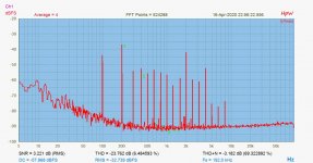
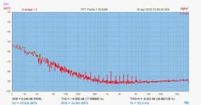
Then changed Ref bypass to PPS, REF resistance to an S102. Then played a multitone signal from like 20cm distance.
First shot is 'standard', second shot is LT3042 'deadened'
With LT3042, Ref bypass cap X7R.
Then changed Ref bypass to PPS, REF resistance to an S102. Then played a multitone signal from like 20cm distance.
First shot is 'standard', second shot is LT3042 'deadened'
Attachments
#3862 measurements - are they for the output on a LT3042 based DC stabiliser board?
WHat is the DUT , what is measured?
//
WHat is the DUT , what is measured?
//
The tests were for 'mapping' an observed vibration sensitivity, while originally I was looking for regulator noise, simply.
The DUT was an LT3042/ LT3094 dual reg, made by ourselves. The signal is taken from the regulated DC output, 4,5V, cca 60mA load.
The setup was: Cookie can >battery> reg. board> Gerhard 's 20x4898 pre at 60dB gain > RTX6001 > HPWorks
The DUT was an LT3042/ LT3094 dual reg, made by ourselves. The signal is taken from the regulated DC output, 4,5V, cca 60mA load.
The setup was: Cookie can >battery> reg. board> Gerhard 's 20x4898 pre at 60dB gain > RTX6001 > HPWorks
microphonics of board and crystal
Nice testing Joseph K
That is precisely why I did my best to isolate the crystal, and the board.
Crystal is mounted in foam block.
board mounted on foam
board covered with layer of sand
whole thing is in a wood box
box is on silicon inside alu chassis
alu chassis on foam
Not scientific but it gives me "sound I find pleasurable". All based on what I learned with WTMC v1.0.
Attachments
In the graphs, one can use the noise floor (the LT3042 output noise power spectra) for reference.
That turned out to be precisely 2nV/sqrtHz, as per datasheet. (in the flat part)
That turned out to be precisely 2nV/sqrtHz, as per datasheet. (in the flat part)
Audio measurements are made in quiet labs with resistive loads and no vibration.
Makes me wonder what is not measured...
Makes me wonder what is not measured...
coax cable
One other thing you could measure.
My sound pleasure meter was also checked wrt coax connection.
Length of coax 1 foot vs 1m made little difference.
RG400 registered slight improvement but not worth the cost or the hassle of the thick cable.
But what does make a difference is the SMA connection. Initial connection finger tight not so good. Torque it down with a wrench and a noticeable uptick in the 'ol pleasure meter. The RF smart crowd will say yes of course. But for those of us in the great unwashed "solder kit crowd" it is worth noting.
Ah, Yes, You are touching an interesting point..
Also the connector sensitivity. Though I have to register here, that I've been doing 'finger tight' connection, but as You can see, with OK results. (I have to keep on using those SMA - s, I am using my fingers for connector 'longevity'.. But I can do a test. My best guess would be that a VNA test would fit here the best.
But, the cables.. I am using an RG178, now. On purpose. Because the cables are rigidly attached to the oscillator PCB.. No way and no sense in mechanical vibration isolation, if then a cable can conduct resonances directly to the board.
So a thin, but good quality RG178 got used.
IMHO you will not pay a penalty for RG178 over RG400 that is worth worrying about. But when you sit to listen critically, you may appreciate wrenched down SMA connectors.
Last edited:
Hello,
I just copied and paste an old post of mine from a month ago i think.
Hello,
SO the way the clocks and the associated circuitry are '' housed '' is a key element in the final result.
I found a 50 mm thick pressed cork panel that i will use to make a kind of sound proof box to isolate the 6 aluminium rectangles.
My intention is to put the supercap in the attachment in between the two trinities and give each unit its own connection to the supercap terminal. SO there will be just one power cable entering the soundproof box. I think giving each unit a cable coming from the outside will/could introduce more vibrations from outside.
In between the 6 rectangles the cork does not have to be as thick.
Of course the boards are '' interconnected '' by the rather rigid coaxial cable. If the circuit is kind of fixed to the frontpanel by the terminal for this cable lots of vibration reducing elements are kind of abolished.
So i think the best idea to wrap all the boards in( carbon foam/ natural fiber????), makes the coaxial connections and slide the boards inside the tube.
If you slide them deeper into the rectangle will the opening on the front have less influence. Of course it will be easy to cover the opening and just leave an opening for the DC supply and the coaxial cables.
I am sure some of these things can be ''determined '' by specific knowledge, most could be measured.
There is a variety of thing you can do to stop the clock from vibrating. The easiest thing is stopping the airborn vibration. And use tin wires to connects the clock to the board is very clever. BUT once there is a kind of firm connection between the SMA terminal and the case( probably you could use a wire between terminal and case to create a prper connection) plus there will be a sturdy cable picking up airborne vibrations and transporting vibrations from one chassis do the other.
It will be like in the old days when people started using garden hose seize cables from their tonearms to their phonostages which would almost destroy all the nice anti feedback ideas in their expensive turntables.
There should me more exchanges of ideas how to handle things like this but it seems also customers find greater joy in getting the latest boards while their old boards never have been used in a proper way.
Greetings, eduard
The DUT was an LT3042/ LT3094 dual reg, made by ourselves. The signal is taken from the regulated DC output, 4,5V, cca 60mA load.
The setup was: Cookie can >battery> reg. board> Gerhard 's 20x4898 pre at 60dB gain > RTX6001 > HPWorks
Try a 4700u / >=25V wet slug tantalum for the pre input and you
get rid of the 30 dB / decade noise rise. And be careful then not to
Zener the op amp inputs. With some luck a good alu elctrolytic might do.
Gerhard
Last edited:
The SMA connections are supposed to be torques to 5 in/lb. You can buy $$$ torque limiting wrenches for that purpose, which I would do if its a critical connection to a MM wave system.
Some of the options are ridiculously expensive- A used HUBER+SUHNER for $100? They are not that exotic. However if you are working with 60 GHz 1.85 mm connectors it would make sense.
I have done that, too!! 🙂
With LT3042, Ref bypass cap X7R.
Then changed Ref bypass to PPS, REF resistance to an S102. Then played a multitone signal from like 20cm distance.
First shot is 'standard', second shot is LT3042 'deadened'
What multitone was that? The spikes appear to be even multiples of 50Hz (mains frequency in yours and your “we” country.
@gerhard & 1audio:
Thanks both for your spectrum analyzer comments ... and since this is a digression to the TWTMC thread just briefly: I think the Red Pitaya and the tinySA both look interesting, however, their basic noise levels appear to be quite high so that what I am looking for may be hidden in the noise. The Red Pitaya is very versatile though ...
The SignalHound on the other hand looks "remarkable" (from my new-to-SA perspective) - 124 dBm basic noise level at 10 Hz and getting better going up in frequency. Could be interesting as well ...
Good suggestions! & clarified about the Timepod in the SA context ...
Thanks again both of you ;-)
Jesper
What multitone was that? The spikes appear to be even multiples of 50Hz (mains frequency in yours and your “we” country.
It is the "Speech" range multitone signal from Arta. And yes, it starts like
"Linearly spaced sine signals from 100 Hz to 500 Hz, plus 1/3 octave
spaced sine signals from 500 Hz to 8 kHz. Phases optimized for crest
factor 10 1 dB."
@Thom
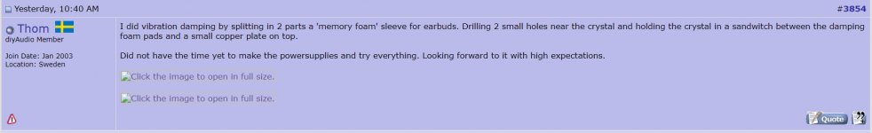
Images you have attached to your posts appear to me as shown below. If I right click on one of the links to open it in a new tab, I am asked for Google Drive logon credentials.
Perhaps if you add the images to your posts as file attachments (using Advanced mode), they could be viewable by more of us 🙂
Attachments
- Status
- Not open for further replies.
- Home
- Source & Line
- Digital Line Level
- The Well Tempered Master Clock - Building a low phase noise/jitter crystal oscillator