Interesting Joseph K
Can I assume PS was a well filtered linear supply with a TPS7A4700, 15V regulator? I use Linear PS/TPS7A4700 set to 16.5V. That would confirm my assumption that there is little to be gained by using a battery at 16.5V vs the TPS7A4700 regulator. Is that a reasonable assumption?
How would you rate TTWMC non cells power supply over a TPS7A board, please. Supercap between the TPSA and the board for the squarer to be always switched on ?
@ all : plus the Hammond box and the "wool" wrapped around the pcb in it, how you guys take care of the close surounding of the crystals, please ? I mean what is the simpliest casual but good enough no placebo to proceed?
Acrylic gel is not for everyone, while it seems sota. I like the earbuds foam way too. How about rubber bands on the crystal can and cotton caps tube for the leads ? Finally how to putt the Hamond box in the cabinet for people not having measurement tools to benchmark the accurate layout strategy ? On foan, on rubber band ? surrounded by corck layer or ... ?
Last edited:
For those that understand electronics pretty well, mechanical vibration of spring-mass systems can be thought of in an analogous way: Electrical Mechanical Analogs - Erik Cheever
The mechanical equivalent of a resistor is called a dashpot:
dashpot - Google Search
Also: https://www.math.utah.edu/~choheneg/Lecture4.pdf
The mechanical equivalent of a resistor is called a dashpot:
dashpot - Google Search
Also: https://www.math.utah.edu/~choheneg/Lecture4.pdf
Hello,
As long as you attach the board to the chassis by means of '' grounding nut '' of the SMA connector your solution will only work in a moderate way.
Probably there are more parts ( i can imagine the coils) on the board that will work not 100 % when being exposed to vibration.
For the 16,5 volt supply i will use a 61,8 F supercap that will be controlled by Doede's intelligent system that will switch from a basic charger to a kind of audiophile style may with a low drop regulator added just before the supercap. I described it before.
The '' designer '' of the 3D printed cel '' cover '' is Italian so maybe Andrea can ship the clocks with the cover included!!
He takes care of that and Ian will make a start with the tutorial before starting a new marketing campaign for his soon to appear product.
Greetings, Eduard
I assume you refer to TWRPS-UGL 15V supply? IMHO it is built for purpose by a skilled person so it is likely the best approach short of his battery option.How would you rate TTWMC non cells power supply over a TPS7A board, please. Supercap between the TPSA and the board for the squarer to be always switched on ?
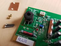
Since I have mentioned my PS, I'll explain the thought process as an example of good enough for purpose at low cost and hi satisfaction of build. I am not an electrical engineer, just a hobbyist. Before retiring I ran a business that designed and built wireless comms supplied to power co's. I depended on 100 engineers to design the products and appreciate their skill and contribution. So I know just enough to know how little skill I have but can have some fun building my own audio system which I find more satisfying than writing a big check to someone else.
With that disclaimer, I chose to build a rudimentary linear power supply from parts on hand because I felt it was good enough. When I tinkered with WTMC v1.0, I did not find a significant impact on sound using different supplies. So I figured a supply with a decent transformer (plitron) a silicon bridge rectifier, Panasonic FC caps, a LM317 prereg and a low noise TPS4700 final regulator was sufficient to supply the clock which Andrea points out is a constant power drain. I used 3rd order clc filtering in case that helped to keep high frequency noise out of it. I have no doubt that proper engineers can point out many flaws in this approach. But I built it with my own hands using free parts that were remains of other builds, and I find the sound pleasant. I do not advocate the design, but perhaps the build vs buy thoughts.
Last edited:
@Thom
Images you have attached to your posts appear to me as shown below. If I right click on one of the links to open it in a new tab, I am asked for Google Drive logon credentials.
Perhaps if you add the images to your posts as file attachments (using Advanced mode), they could be viewable by more of us 🙂
Ah, thanks for the heads-up Mark.
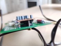
I attach the images of my take on crystal vibration damping here:
Attachments
Nice work Thom, Could you post a circuit diagram ? Do you Shell These or make the Gerber available?
Another passion,same fight.
Vibration Damping Materials Comparison Revisited for Quadcopter FPV & Aerial Camera Setups - YouTube
Vibration Damping — Copter documentation
I will place my case on these wire rope isolator Mini cable en acier inoxydable pour Drone RC, 1 piece, cable d'amortissement pour photographie, accessoires de camera a cardan | AliExpress
dddac,
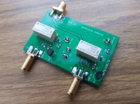
I did pretty much the simplest possible circuit, just a nonlatching signal relay for each clock. The activated relay will need some 40 mA. Did not have the space for Andrea's switchboard within my DAC so I made this and will combine it with one of Andrea's squarer boards. If it fits in your application I have a small number of leftover boards, I could send you one if you want to try it out, just PM me.
I did pretty much the simplest possible circuit, just a nonlatching signal relay for each clock. The activated relay will need some 40 mA. Did not have the space for Andrea's switchboard within my DAC so I made this and will combine it with one of Andrea's squarer boards. If it fits in your application I have a small number of leftover boards, I could send you one if you want to try it out, just PM me.
Attachments
dddac,
I did pretty much the simplest possible circuit, just a nonlatching signal relay for each clock. The activated relay will need some 40 mA. Did not have the space for Andrea's switchboard within my DAC so I made this and will combine it with one of Andrea's squarer boards. If it fits in your application I have a small number of leftover boards, I could send you one if you want to try it out, just PM me.
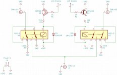
one or two things that may be worth checking.
better to switch the coil with positive voltage and keep one side grounded.
the positive side can be bypassed with a cap also to gnd.
that ensure a path towards ground and let the coil act as a shield.
an RF relay, while more expensive, can ensure proper impedance matching.
What is the startup time of these oscillators?
I mean, two oscillators with an ENABLE input each would remove the need for switching...
I mean, two oscillators with an ENABLE input each would remove the need for switching...
one or two things that may be worth checking.
better to switch the coil with positive voltage and keep one side grounded.
the positive side can be bypassed with a cap also to gnd.
that ensure a path towards ground and let the coil act as a shield.
an RF relay, while more expensive, can ensure proper impedance matching.
Yes, good point, thanks.
What is the startup time of these oscillators?
I mean, two oscillators with an ENABLE input each would remove the need for switching...
The 5/6 MHz oscillators need 5 to 10 seconds to start.
There is no way to put them in high impedance state so the only option is a relay.
The Enable pin could be implemented after the conversion into square wave using a LVC1G126 but it will add noise.
Ideally you would want isolation amps to keep the oscillators from interacting with each other. NIST has a design https://tf.nist.gov/general/pdf/498.pdf that's good at dealing with this. You may be able to create a disable/tristate in them. The RF relays are good but expensive.
The 5/6 MHz oscillators need 5 to 10 seconds to start.
OK, that answers the question then.
Oscillators need time for jitter/phase-noise to stabilize, which can at least be a few days. IIRC some measurements indicate it can take weeks. For some clocks at least, using the built-in enable/disable function is just as bad for jitter as powering the clock off. Gold contact signal relays don't seem to have that downside.
In addition, listening tests were done here to find out if clocks audibly interacted with each other if switched by signal relays. A disabled/powered-off clock and one live clock, was compared with having two live clocks switched by relays. No audible difference was detected, at least not with the present state of the dac.
In addition, listening tests were done here to find out if clocks audibly interacted with each other if switched by signal relays. A disabled/powered-off clock and one live clock, was compared with having two live clocks switched by relays. No audible difference was detected, at least not with the present state of the dac.
Last edited:
... well, how much farads a close low impedance supercap is needed in order the crystal stays on while the rest of the DAC is off... for saying: 15 days circa?
knowing it needs 3 days to stabilize a crystal that are not powewered anymore- ?
I mean for whom not wanting to use LiFePo.
knowing it needs 3 days to stabilize a crystal that are not powewered anymore- ?
I mean for whom not wanting to use LiFePo.
Some dac designs (e.g. Topping D90) do not turn off power by default. The front panel power switch and the remote control on/off function merely put the dac in standby (turn off the display, and mute the outputs). Unless there is a power failure or human intervention to similar effect, the dac mostly stays warmed up and ready to play music.
- Status
- Not open for further replies.
- Home
- Source & Line
- Digital Line Level
- The Well Tempered Master Clock - Building a low phase noise/jitter crystal oscillator