Actually it has two enable pins for the two outputs (Named SD1/2 on pins 12 and 7). See datasheet page 16.
Yes, but they are not tri-state, so there is no way to put the outputs in high impedance state.
In other words you will have a short circuit to ground.
In other words you will have a short circuit to ground.
Agreed.Otoh to rely on listening tests without proper controls might be not sufficient for any external observer
In this case, "reality" being marketing.but could be a better fit for reality.
You've been conversing on audio related forums for +- 20 years. You would know what constitutes extraordinary claims.The "extraordinary proof" is a nice idea, but often it is questionable what constitutes a "extraordinary claim" and further if any of the requested "proof" is even possible (considering the human nature), especially if no one is able to write down which kind of "proof" he would accept as sufficient evidence.
Yes, but they are not tri-state, so there is no way to put the outputs in high impedance state.
In other words you will have a short circuit to ground.
Yes, you're right. Didn't have than in mind.
I just looked at RF relais at mouser and they state an attenuation of only 30dB per contact. Seems rather low to me, who wants to have a -30dB 24MHz signal on his 22MHz clock... (just examples). Do you have any recommendations for properly isolating RF coaxial relays?
In the FSDO only one signal crosses one relay.
We have used the "T" configuration to switch between the clocks, so one relay manages one clock.
We have used the "T" configuration to switch between the clocks, so one relay manages one clock.
Yes, I was planning to do that also, but still there's some (probably mainly capacitive) over the open contacts. Don't you fear that the residual throughput will pollute the active clock?
The relais are DPDT dual coil latching type, so the unused clock is terminated to ground with 50R with the first relay, while the second relay is open.
The only thing you should care is a proper distance in the layout to keep the clocks as far as possible.
The only thing you should care is a proper distance in the layout to keep the clocks as far as possible.
I recently made a small clock board to switch the sine signal from 2 clocks.
An externally hosted image should be here but it was not working when we last tested it.
Nice. Now it would be nice to be able to measure it's effect on the switched output..
I could send you a board if you are in Europe and have the time and equipment to measure it? I don't have anymore relays though.
I would be very interested in knowing if it degrades the signal.
I'm no RF guy, so probably far from optimal design.
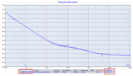
In the meantime I had made a ~first measurement of the TWTMC DRIXO 22,579MHz clock.
In isolation, both thermal and mechanical.
There is that upper range resonance, which I left in here, because for optimizing for that, I should dismount, experiment (with grounding, schielding, it's an interaction between the oscillator and it's environment. In the Hammond box it appears to be less)
Also, here the first time I have started to note the importance of a good power supply. Present shot was taken with a TPS7A4700, 15V regulator.
Mechanical vibrations to be excluded.
If these requirements satisfied - - I see an optimal agreement, again, with Andrea's measurement, in the low frequency, close-in zone..
There is a deviation in the 100Hz region. I feel that "hump" in that zone appears in Andrea's, Roberto's and lastly even Gerhard's measurements, so could it be a kind of feature of the Timepod kit used..?
Attachments
Last edited:
Interesting Joseph K
Can I assume PS was a well filtered linear supply with a TPS7A4700, 15V regulator? I use Linear PS/TPS7A4700 set to 16.5V. That would confirm my assumption that there is little to be gained by using a battery at 16.5V vs the TPS7A4700 regulator. Is that a reasonable assumption?
Can I assume PS was a well filtered linear supply with a TPS7A4700, 15V regulator? I use Linear PS/TPS7A4700 set to 16.5V. That would confirm my assumption that there is little to be gained by using a battery at 16.5V vs the TPS7A4700 regulator. Is that a reasonable assumption?
I did vibration damping by splitting in 2 parts a 'memory foam' sleeve for earbuds. Drilling 2 small holes near the crystal and holding the crystal in a sandwitch between the damping foam pads and a small copper plate on top.
Did not have the time yet to make the powersupplies and try everything. Looking forward to it with high expectations.
Did not have the time yet to make the powersupplies and try everything. Looking forward to it with high expectations.
An externally hosted image should be here but it was not working when we last tested it.
An externally hosted image should be here but it was not working when we last tested it.
Interesting Joseph K
Can I assume PS was a well filtered linear supply with a TPS7A4700, 15V regulator? I use Linear PS/TPS7A4700 set to 16.5V. That would confirm my assumption that there is little to be gained by using a battery at 16.5V vs the TPS7A4700 regulator. Is that a reasonable assumption?
Hello,
Doede will test my clock boards with my 61.8 F supercap in a few weeks time using a separate supply to charge the cap up to 16,8 volt and a audiophile style style to keep the voltage at 16,5 volt to '' feed '' the clocks.
Greetings, eduard
Interesting Joseph K
Can I assume PS was a well filtered linear supply with a TPS7A4700, 15V regulator? I use Linear PS/TPS7A4700 set to 16.5V. That would confirm my assumption that there is little to be gained by using a battery at 16.5V vs the TPS7A4700 regulator. Is that a reasonable assumption?
Yes, I am using a linear (lab) PS /TPS7A4700_15V config. I did try a Pb battery, 12V, but I got sligthly higher noise floor) (very probably because if the lower PS).
Earlier on I did try to look for PS voltages between 15V--17V, and did not see great differences..
I measure 69mA PS current.
Thanks Joseph
I note that your test and Andrea's appear to show the same results. His was tested at 16.5V using Lithium PS and yours at 15V with a low noise reg. Seems to confirm phase noise not materially impacted by the battery supply. Then we'll soon have Doede's subjective report based on a supercap based supply. Useful for those still planning their build.
I note that your test and Andrea's appear to show the same results. His was tested at 16.5V using Lithium PS and yours at 15V with a low noise reg. Seems to confirm phase noise not materially impacted by the battery supply. Then we'll soon have Doede's subjective report based on a supercap based supply. Useful for those still planning their build.
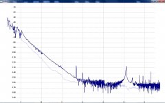
Now.. Only for fun!!
I have noticed that Andrea's design is somehow sensitive to vibrations. I did have to try to isolate, because low freq rumble (~cars passing outside..) did have an influence on the response..
So it came the curiosity, how do it react (in this, isolated way..) to acoustic excitation?
Achtung, very far from scientific trial..
just a speaker placed at ~1m from the table with the setup+oscillator. 4W power, series of single 57Hz, 70Hz tones played. Speaker is about 85dB sensitivity. 4W neans 6dB +, so we are at about 91dB level. +_, !!
Attachments
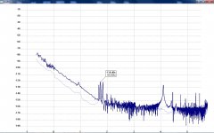
Those microphonics could be from the circuit board, components and transistors as well as the crystal. Anyplace where you have a higher impedance and a voltage bias with some capacitance a little flex and you have a microphone. The modulation is -118 dB below the capacitance being modulated, so not much.
- Status
- Not open for further replies.
- Home
- Source & Line
- Digital Line Level
- The Well Tempered Master Clock - Building a low phase noise/jitter crystal oscillator