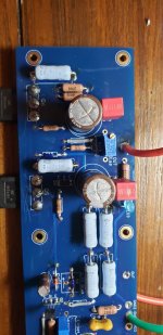
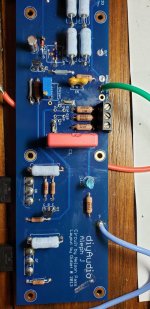
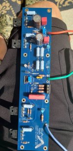
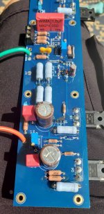
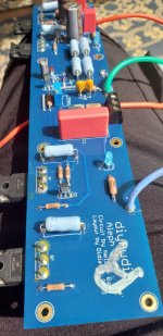
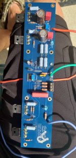
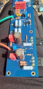
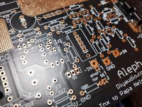
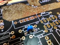
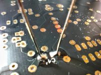
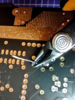
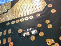
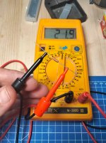
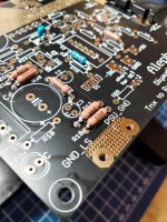
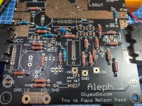
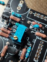
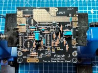
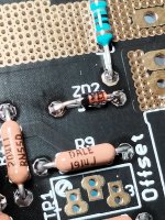
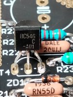
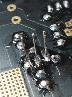
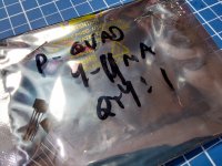
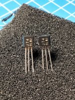
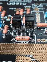
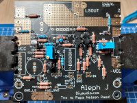
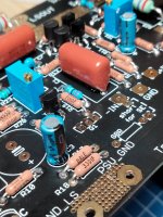
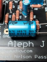
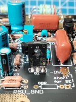
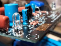
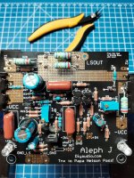
I see a burned/damaged component beside C1 (the big red cap). Did that occur as a function of the failure? or while removing Q1A/B? Or is that a jumper? It's been a while since i looked at my own.
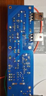
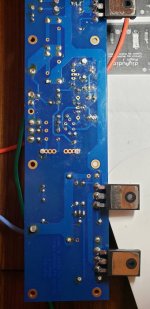
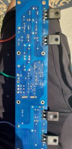
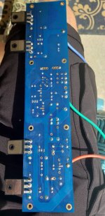
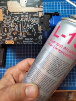
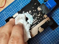
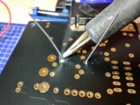
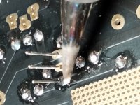
Any chance you have some denatured or isopropyl alcohol and a toothbrush? If you could scrub the flux residue off the backside of the board it will help us see if there are any connection problems.
Any chance you have some denatured or isopropyl alcohol and a toothbrush? If you could scrub the flux residue off the backside of the board it will help us see if there are any connection problems.
Chris,
It looks to be the insulation of the jumper was melted off in attempts to resoldering and/or removing the J74 JFETS which are part of the input stage (differential long tailed pair).
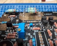
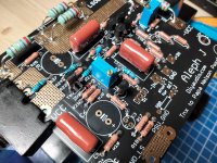
Just on a cursory look, I see several cold soldered joints. A board devoid of flux and debris would make it easier to discern where the problems lie. Chris’ advice is good.
Best,
Anand.
Last edited:
KP, I also agree with Chris and Anand's suggestion that the board be cleaned to allow for a better visual inspection.
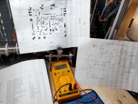
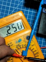
I assume this is the board with the funny R7 voltage measurement.
Since you've managed to measure good Idss values with your jfets, it's
quite possible some cleaning and carefully resoldering will get this channel
working.
I assume this is the board with the funny R7 voltage measurement.
Since you've managed to measure good Idss values with your jfets, it's
quite possible some cleaning and carefully resoldering will get this channel
working.
Last edited:
Last edited:
Very nice work Peppennino!
I wish I had ZM's Aleph J boards too. I doubt he has any more left!
Best,
Anand.
I wish I had ZM's Aleph J boards too. I doubt he has any more left!
Best,
Anand.
These look like a good set of boards to have in the store. Some nice and worthwhile changes to the basic circuit.
I can see stuffing these with a pair of my favorite Mosfets, cranking the voltage and bias current until the amp is about to melt, then backing off just a smidge. 😉
I can see stuffing these with a pair of my favorite Mosfets, cranking the voltage and bias current until the amp is about to melt, then backing off just a smidge. 😉
These look like a good set of boards to have in the store. Some nice and worthwhile changes to the basic circuit.
I can see stuffing these with a pair of my favorite Mosfets, cranking the voltage and bias current until the amp is about to melt, then backing off just a smidge. 😉
Yup! I really like the interesting twist he did on the input stage judging from Peppennino's schematic pic. And...using IRFP150's on the outputs which minimizes the matching concerns of the original design with the IRFP 240's.
Best,
Anand.
Boards in beta test are undergoing testing. They might not pass the tests (!!) If they don't pass then nobody wants them in the Store. So, the only things a bystander can do at the moment, are: be patient, cross your fingers, light a candle, eat your vegetables, say your prayers, be polite to others, and hope the beta tests give excellent results.
I am absolutely delighted with the result using this PCB!
Feeling blessed having the opportunity to own it!
Thanks again to all involved and especially to the Mighty One and 6L6!
- Alvis
Feeling blessed having the opportunity to own it!
Thanks again to all involved and especially to the Mighty One and 6L6!
- Alvis
same as Divine Author is behaving


 Oh, Dee Wine
😀
Seriously... ZM's pcb look superb! 🙂
Last edited:
Last edited:
- Home
- Amplifiers
- Pass Labs
- Aleph J illustrated build guide
