Please let me ask for a tip about how to connect the internal wiring to the power inlet. Is it crimped, soldered, etc.?
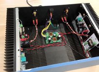
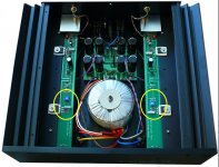
Here is my Ship of Theseus. It is compatible with the DIY-VFET lottery amp, but it contains zero original DIY-VFET elements. It's got a different chassis (Modushop Deluxe), different supply filter, different front end boards (Relentless), different output stage boards (EF-PNP), even a different power switch (Mouser P/N 633-JWL11BC2A-A).
It's a test fixture to try out different options and to test inter-operability. Eagle eyed viewers can see evidence of this: the blue masking tape on the front panel, the "two left shoes" (non mirror image) amp channel PCBs, the use of ferrules on some but not all Euroblox connectors, and so forth.
This week I'm using it for listening tests of different front end cards and different loudspeakers. A very pleasant chore!
_
It's a test fixture to try out different options and to test inter-operability. Eagle eyed viewers can see evidence of this: the blue masking tape on the front panel, the "two left shoes" (non mirror image) amp channel PCBs, the use of ferrules on some but not all Euroblox connectors, and so forth.
This week I'm using it for listening tests of different front end cards and different loudspeakers. A very pleasant chore!
The Ship of Theseus is an artifact in a museum. Over time, its planks of wood rot and are replaced with new planks. When no original plank remains is it still the Ship of Theseus?
_
Attachments
An interesting take on the development platform.
Do my eyes detect a small inductor on the OS boards?
Where did you acquire the DIN style DC power inlet connector?
Do my eyes detect a small inductor on the OS boards?
Where did you acquire the DIN style DC power inlet connector?
Nice work, Mark! We don’t often get to see photos of your amps.
I see you are using pin crimped tips on your leads into the terminal blocks. Nice. Ever since I have started using them, I’m never going back to bare soldered wire or bare wire in screw terminal blocks again.

On LuFo:
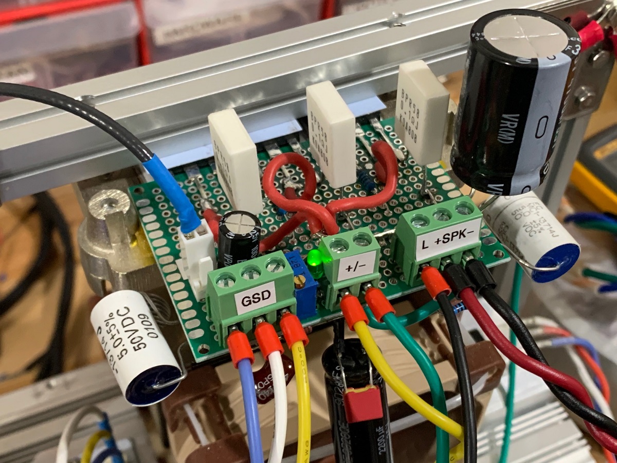
I see you are using pin crimped tips on your leads into the terminal blocks. Nice. Ever since I have started using them, I’m never going back to bare soldered wire or bare wire in screw terminal blocks again.
On LuFo:
Last edited:
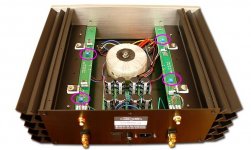
Nice work, Tubgsten! Is that a standalone active bridge/CRC/Cap Mx single rail dual mono PSU?
Here is my Ship of Theseus. It is compatible with the DIY-VFET lottery amp, but it contains zero original DIY-VFET elements. It's got a different chassis (Modushop Deluxe), different supply filter, different front end boards (Relentless), different output stage boards (EF-PNP), even a different power switch (Mouser P/N 633-JWL11BC2A-A).
It's a test fixture to try out different options and to test inter-operability. Eagle eyed viewers can see evidence of this: the blue masking tape on the front panel, the "two left shoes" (non mirror image) amp channel PCBs, the use of ferrules on some but not all Euroblox connectors, and so forth.
This week I'm using it for listening tests of different front end cards and different loudspeakers. A very pleasant chore!
_

Nice job Mark , you could have turn your psu filter board 90 ° right , for say , a better symmetry 😉
.
^ xrk, of course it is 😉
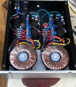
Transformers are Triad 160VA with 15V / 30V secondaries, tied for 30V.
PSU boards are currently adjusted to deliver 36.5V into a 23 Ohm load. Some tweaks of the CFP (cap multiplier) control circuit were implemented to optimize voltage range for these transformers and the expected 1.6A load.
Transformers are Triad 160VA with 15V / 30V secondaries, tied for 30V.
PSU boards are currently adjusted to deliver 36.5V into a 23 Ohm load. Some tweaks of the CFP (cap multiplier) control circuit were implemented to optimize voltage range for these transformers and the expected 1.6A load.
Mine needs a wee bit over 1.8 amperes per channel. I'm using bias circuits that are, uh, very similar to the VFET's bias-current-setting circuitry.
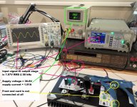
In the picture below the input signal to the PNP emitter follower output stage, is 7.071V RMS. That's 20 volts from peak to trough, and that's the most my signal generator will deliver at 50 kHz. If the emitter follower output stage's gain is 0.95X {somewhat higher than the VFET's} that's 5.6W RMS to the 8 ohm dummy load resistor. Fortunately all front end cards are capable of delivering MUCH more than 7V RMS. Edcor step-up transformers are pretty good at doing their job.
So I recommend using a PSU that's good for at least 4A total. The Mean Well in the VFET lottery kit is rated for 4.44 amperes (160 watts at 36V) so it's just fine. Interested parties can check the datasheet of the supply filtering inductor that shipped with the kit, to re-verify that it's rated to carry more than 4A. The inductors in the filter I'm using in the Ship Of Theseus amplifier (post #1283), which are NOT the same as the ones in the kit, are rated for more than 7 amperes. To name one example.
_
Attachments
Good idea!
Seems some trimpots uses a brush as wiper and other (Bourns) uses "multi-wire":
Trim potentiometers – Passive Components Blog
Those "BI-Technology" trimmers are they "also" quality trimmers?
Seems the "BI-Technology" multiturn trimmer uses a brush as wiper but have no idea if this is good or bad.....
Buy a pair of every trimmer models and try how is quiet inside of the amplifier circuit 🙂
That is the best way to ensure there are no issues with wiper contact.Or solder verticaly high precision two resistors instead of trimmer pot..
I will consider this. Then I will also get theory confirmed or not if trim pot was the issue. Then I should do it for both channels. Even if trim pot was not the issue it will be an "upgrade" of the amp and 19.9 - 20.1 VDC range will probably be ok.
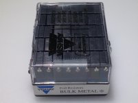
Here are photos of the commercial products "M2" and "F5" sold by First Watt, at a price around USD 3500 per amplifier. M2 has one trimmer potentiometer per channel and F5 has two trimmers per channel. They appear to be the very same trimmer potentiometers used by hundreds of DIYers in the Amp Camp Amp. If so then you could check the official ACA parts list to find out which trimmers are approved and blessed by the engineers who make the decisions at First Watt.
_
_
Attachments
vishay metal foil trimmer low noise
I have those in my F6 , perfect in any situations 😉
.
It's addictive how quiet can be this Vfet amp.
Incredible low background noise floor level.
It's search of perfection of the both channels..
my hope Meper can find what component or phenomena was the tiny problem.
Yes I have used 10K Accutrim in other amp..exotica and cost is high
In stock https://www.mouser.fr/ProductDetail...Y006910K0000J0L?qs=Omyi%2BwOkBJUNGGEwoZxXug==
http://www.vishaypg.com/docs/63054/Accutrim_1260_RJ24.pdf
Incredible low background noise floor level.
It's search of perfection of the both channels..
my hope Meper can find what component or phenomena was the tiny problem.
vishay metal foil trimmer low noise
Yes I have used 10K Accutrim in other amp..exotica and cost is high
In stock https://www.mouser.fr/ProductDetail...Y006910K0000J0L?qs=Omyi%2BwOkBJUNGGEwoZxXug==
http://www.vishaypg.com/docs/63054/Accutrim_1260_RJ24.pdf
Attachments


Last edited:
- Home
- Amplifiers
- Pass Labs
- DIY Sony VFET Builders thread