My TestBench
Hi Guy's
Attached is my test bench. Fee free to give it ago.
It's basically the one Sandro created, just modified to suit the Wolverine with some other calculated information I added as well.
Please refer to Sandro's video series on YouTube if you have trouble driving it.
I know OS posted some test results but I don't think he
quoted what power level he was testing it at.
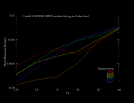
I have set the test bench to 100W into 8 ohms with 64v Rails
I set the IPS LTP CCS and VAS CCS as per the schematic text.
I set the Bias to achieve 26mV across the emitter resistor.
The 1K distortion looks great as expected. But the 20K is a bit higher that I would have thought.
I question OS's choice of IPS LTP Degeneration resistors 47 ohms only gives an degeneration factor of about 4.4.... The HB was about 7 and BC recommends about 10.
Hi Guy's
Attached is my test bench. Fee free to give it ago.
It's basically the one Sandro created, just modified to suit the Wolverine with some other calculated information I added as well.
Please refer to Sandro's video series on YouTube if you have trouble driving it.
I know OS posted some test results but I don't think he
quoted what power level he was testing it at.
I have set the test bench to 100W into 8 ohms with 64v Rails
I set the IPS LTP CCS and VAS CCS as per the schematic text.
I set the Bias to achieve 26mV across the emitter resistor.
The 1K distortion looks great as expected. But the 20K is a bit higher that I would have thought.
I question OS's choice of IPS LTP Degeneration resistors 47 ohms only gives an degeneration factor of about 4.4.... The HB was about 7 and BC recommends about 10.
Attachments
Increasing LTP resistors will increase thd. Set bias for about 60-70mA per device. I never simmed the wolverine.
Do you happen to know the audibility of a few PPM distortion compared to say 10% overshoot? If not then how do we decide on TPC vs TMC?
Thanks for raising that. I'd been neglecting overshoot on the thinking that "it's 1dB at 1MHz, who cares." But that's wrong: TPC can produce 2-3dB of bump in the closed loop gain plot at 250kHz. Not that far above the audio band.
How do we decide indeed.
There seem to be two overshoot mechanisms:
Small signal peak: In an AC sim, the output rail peaks at +/-1dB at ~250kHz. More aggressive TPC yields a taller peak. It's "cheating" but we can remove that peak by upgrading the RF filter in the input network to 2nd order. Now if we apply a small-signal step function to the input, there's no overshoot.
Large signal overshot: with that 2nd order RF filter in place, larger squarewaves (tens of volts) still overshoot. This happens when the amp tries to slew faster than it can -- turning the VAS completely off or running it at "wide open throttle" trying to catch up during over-slew. In these conditions, voltages at the compensation cap terminals bounce outside their normal bounds (as the VAS transistors' bases fall to near the negative rail, or climb a few volts above their normal level.) As the machine stabilizes, the comp caps must discharge the voltages they've accumulated and the output jumps around before settling down.
TMC is also prone to some large signal overshoot. The shape of the waveform looks a little different but it draws some kinks on overslew.
Over-slew shouldn't happen when playing real program material. It can happen on the bench. It can happen when you plug in some RCAs at the back panel. Maybe it happens at power on? But not at steady state. (Or is that too optimistic?) The circuit should recover from over-slew, and quickly, but I would guess the shape it draws isn't an audibility concern since it shouldn't arise when we're listening.
That leaves the question of whether the small-signal peak is audible. I don't know. If it is, we could fix it with a 2nd order filter at the input.
ps. I went looking for a hybrid of TMC and TPC-- something with less peaking than TPC and more loop gain at the IPS than TMC -- and no reduction in distortion performance or loopgain over the OPS. I found one, though it's only marginally better on either dimension. A starting point for more "R&D"? I'll write that up later.
"ps. I went looking for a hybrid of TMC and TPC-- something with less peaking than TPC and more loop gain at the IPS than TMC -- and no reduction in distortion performance or loopgain over the OPS. I found one, though it's only marginally better on either dimension. A starting point for more "R&D"? I'll write that up later."
Please let us know what you found.
Please let us know what you found.
I think it was Dadod here who showed OITPC which I suspect may be relevant to those goals. Although I can't get the latest Wolverine simulation running because it is missing the loopgain probe symbols.
Sorry Keantoken, I forgot to include that. I'll post another zip soon.I think it was Dadod here who showed OITPC which I suspect may be relevant to those goals. Although I can't get the latest Wolverine simulation running because it is missing the loopgain probe symbols.
Updated Zip with Loop gain probe
This should would. Please let me know if you have any issues.
Just put the LG_single.asy & LG_single.asc files in your LTspiceXVII folder under your username.
example .......\Documents\LTspiceXVII\lib\sym
Theoretically it should work, if those files are in the same folder as the workbench file but its best to keep those sort of things in the LTspice symbol library.
I think it was Dadod here who showed OITPC which I suspect may be relevant to those goals. Although I can't get the latest Wolverine simulation running because it is missing the loopgain probe symbols.
This should would. Please let me know if you have any issues.
Just put the LG_single.asy & LG_single.asc files in your LTspiceXVII folder under your username.
example .......\Documents\LTspiceXVII\lib\sym
Theoretically it should work, if those files are in the same folder as the workbench file but its best to keep those sort of things in the LTspice symbol library.
Attachments

Splendid work stuartmp
I am impressed with THD @ 20khz 50W..... really good
But looking at your schematic I see R17 (15k).... It is good to limit current in the VAS buffer Q12 but it might affect SR.
I experimented that approach and got nimble bass with such a high collector resistor for Q12.
I ended up with a very low value (2k2) for R17 and added a 1N4149 between the collectors of Q4 and Q3... this clamp provides clean clipping and I do not need the other diode (D3 BAV21).
THD is lower also.
Please let me know what you think.
Oh yeah -- I reinvented dadod's OITPC. There's nothing new under the sun!
I started with plain TPC. Then connected a "Cherry" cap from the output rail to the VAS input. The size of this cap controls the in-band loop-gain over the IPS, you can select it anywhere between ~30db and ~60db.
Then add a series resistor so the Cherry cap doesn't reduce stability margins >1MHz.
That's already pretty good at reducing the AC response peak, though it's not totally gone. I set loopgain over the IPS at ~40dB.
Getting crazy now: you can split the Cherry cap into its own little TPC network, to yield a few more dB of in-band loop gain over the IPS without making peaking worse.
It looks complex, but the sim is good. Minimal overshoot, 44db of in-band loopgain around the IPS, 56db around the OPS. It's easy to find values that work, surprising for the complexity of the network.
That's enough "adventures in R&D" for today. To be clear, this isn't a proposal -- I'd more likely build with plain old TPC and a 2nd-order RF filter at the input. That stops the small-signal overshoot and preserves all ~60dB of loopgain around the IPS. Probably not a bad idea anyway to "tune out" radio noise!
Attachments

Last edited:
Splendid work stuartmp
I am impressed with THD @ 20khz 50W..... really good
But looking at your schematic I see R17 (15k).... It is good to limit current in the VAS buffer Q12 but it might affect SR.
I experimented that approach and got nimble bass with such a high collector resistor for Q12.
I ended up with a very low value (2k2) for R17 and added a 1N4149 between the collectors of Q4 and Q3... this clamp provides clean clipping and I do not need the other diode (D3 BAV21).
THD is lower also.
Please let me know what you think.
I completely agree and yes it does reduce the distortion.
I don't think there enough currently flowing through D8 either. I had trouble with this on my HB.
Currently D8 has 2.3mA flowing through it which is less that 20% of the maximum if R6 is changed to 10k then we should get around 3.45mA which is approximately 20.7%
This change also lowers the distortion a little more.
I will have more time on the weekend to investigate. I usually like to step the output transistor bias voltage first to get the best result there as this can mask other potential improvements throughout the circuit if its not at its lowest.
Looks like a setting of OPS_RBias to around 178 so RE drop is 13.5 mV is close to ideal for these transistors.
This lowered the distortion from 0.0017% to 0.001%
I have also found this on the bench with my HB 16mV was ideal. Far away from the Oliver condition of 26mV
Even though the use of a base stopper resistors will lower the Oliver condition somewhat.
Last edited:
Though I might just ask the question.
Does anyone know where OS is?
His last post was on the 16th of May
Does anyone know where OS is?
His last post was on the 16th of May
Last edited:
Here is a chart I made years ago which seems relevant. Note that it is only the 3rd harmonic.
Notice that at 26mV temperature drift doesn't make much difference whereas at 10mV degeneration, just 2mV has an enormous effect. At lower degeneration voltage you need better bias stability.
Notice that at 26mV temperature drift doesn't make much difference whereas at 10mV degeneration, just 2mV has an enormous effect. At lower degeneration voltage you need better bias stability.
Attachments
Last edited:
Very good point. I did notice that. As you lower the RE voltage drop the distortion comes down slowly but go to far and it very rapidly rises. Thank you for providing more clarity to this.Here is a chart I made years ago which seems relevant. Note that it is only the 3rd harmonic.
Notice that at 26mV temeprature drift doesn't make much difference whereas at 10mV degeneration, just 2mV has an enormous effect. At lower degeneration voltage you need better bias stability.
I guess right now if myself and others are simulating other circuit mods we can temporarily set the RE voltage to this level knowing it will provide low distortion.
My RE voltage in the post above should have been 17.1 mV
Though I might just ask the question.
Does anyone know where OS is?
His last post was on the 16th of May
I remember him saying he was moving and to expect radio silence for a month or so...
Is the BOM more or less finalized? Be fun to start shopping... I was also planning on about 70v rails, were some components (992 and 1845 I believe) changed to a lower voltage part due to availability? Using a couple transformers from an older NAD AV amp.
Oh yeah -- I reinvented dadod's OITPC. There's nothing new under the sun!
I my opinion OITPC is working better with low impedance feedback network, and I use it im my CFA mostly, and yes, with symmetrical VAS and VAS emitter resistor RC bypassed to improve PM. No LG peaking.
Damir
“ I have also found this on the bench with my HB 16mV was ideal. Far away from the Oliver condition of 26mV”
I did a lot of work on this on my Model 1721 power Amp. I was always of the opinion the quiescent current had to strictly obey the Oliver criteria for lowest distortion. However, what I found is that minimum distortion (this is of a complete amplifier with global feedback) is actually like a bathtub - in my case with 0.33 Ohm degeneration resistors and 4.7 Ohm base stoppers, the Iq for minimum distortion is from about 25 mA through to about 90 mA. I ended up biasing each pair up at about 35 mA. YMMV.
Ovation High Fidelity - Model 1721
Hi Guy'sI my opinion OITPC is working better with low impedance feedback network, and I use it im my CFA mostly, and yes, with symmetrical VAS and VAS emitter resistor RC bypassed to improve PM. No LG peaking.
Damir
So what unity gain crossover frequency are you aiming for?
Looks like OS is aiming for 1.2Mhz
1/2 x pi x rltp x ACL x Cm
1/2 x 3.14159 x 60.86 x 27 x 82.47E-12
= 1,174,502.233 Hz or approximately 1.2MHz
It this what your aiming for with your TPC testing?
OS is using 100p and 470p for his compensation capacitors the same as the HB.
I was about to use 56p and 330p on my HB. This gave me a unity gain crossover frequency of 750Mhz with about 88° of phase margin.
The Input high pass filter on the wolverine is approximately 1.6Mhz
And the HB was approximately 720Khz
Last edited:
I remember him saying he was moving and to expect radio silence for a month or so...
Is the BOM more or less finalized? Be fun to start shopping... I was also planning on about 70v rails, were some components (992 and 1845 I believe) changed to a lower voltage part due to availability? Using a couple transformers from an older NAD AV amp.
I'm back. Central ave. , Albany , NY.
OS
I'm back. Central ave. , Albany , NY.
OS
Welcome back OS, I hope that your move went well and your enjoying getting to know your new surroundings.
When you have time please review from post #1018.
Did you get the files that I sent to your personal email address?
Last edited:
I have not been online for 2 weeks.
I really love that final posting of the OPS with the alternative inductor placement.
I also like the changes/options to the Wolverine.
I appreciate the input in regards to the present IPS. But , modular means variety.
Being introduced to many designs (and SMT) is the end goal of
this project.
OS
I really love that final posting of the OPS with the alternative inductor placement.
I also like the changes/options to the Wolverine.
I appreciate the input in regards to the present IPS. But , modular means variety.
Being introduced to many designs (and SMT) is the end goal of
this project.
OS
- Home
- Amplifiers
- Solid State
- DIYA store "Wolverine" (Son of Badger) .... suggestions ??