Let's check the stability of the wolverine from comment #612:

That 7MHz "hump" eats into gain margin which is a bit less than 10 db. Kinda skimpy -- can we do better?
Here's TPC, plus a lead cap, plus a zero added to the OPS:

Now we're cookin with gas: 70 degree phase margin, 20db gain margin. This is radically stable:

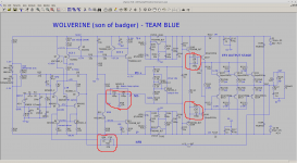
That output stage zero idea is "stolen" from the NAD 2600A. My 2600A is a long time survivor. (They're "Not All Defective.")
TPC puts all that loopgain around the input stage too -- probably around 20db more than TMC does at treble freqs.
That keeps input stage signal current in the nanoamp range even when driving rail-to-rail output. We know from Self's work that DC current balance is super important for input stage linearity. Why would we allow AC currents to take it out of balance? Why make the IPS charge and discharge a bigass miller cap or TMC network? It doesn't have to -- this is the magic of TPC.
That 7MHz "hump" eats into gain margin which is a bit less than 10 db. Kinda skimpy -- can we do better?
Here's TPC, plus a lead cap, plus a zero added to the OPS:
Now we're cookin with gas: 70 degree phase margin, 20db gain margin. This is radically stable:
That output stage zero idea is "stolen" from the NAD 2600A. My 2600A is a long time survivor. (They're "Not All Defective.")
TPC puts all that loopgain around the input stage too -- probably around 20db more than TMC does at treble freqs.
That keeps input stage signal current in the nanoamp range even when driving rail-to-rail output. We know from Self's work that DC current balance is super important for input stage linearity. Why would we allow AC currents to take it out of balance? Why make the IPS charge and discharge a bigass miller cap or TMC network? It doesn't have to -- this is the magic of TPC.
Attachments
Last edited:
Let's check the stability of the wolverine from comment #612:
That 7MHz "hump" eats into gain margin which is a bit less than 10 db. Kinda skimpy -- can we do better?
Here's TPC, plus a lead cap, plus a zero added to the OPS:
Now we're cookin with gas: 70 degree phase margin, 20db gain margin. This is radically stable:
That output stage zero idea is "stolen" from the NAD 2600A. My 2600A is a long time survivor. (They're "Not All Defective.")
TPC puts all that loopgain around the input stage too -- probably around 20db more than TMC does at treble freqs.
That keeps input stage signal current in the nanoamp range even when driving rail-to-rail output. We know from Self's work that DC current balance is super important for input stage linearity. Why would we allow AC currents to take it out of balance? Why make the IPS charge and discharge a bigass miller cap or TMC network? It doesn't have to -- this is the magic of TPC.
Insert 100nH to 200nH of parasitic inductance in the collectors of the outputs and recheck stability. Bypassing for the outputs is on one side of the board. The parasitic inductance might be higher at the far side of the board.
Last edited:
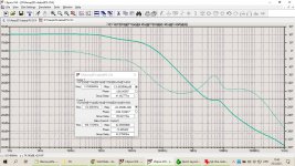
Here's the .asc for the original circuit and modded circuit (of comment 1041), plus the loopgain probe. Just simulate and plot the loopgain expression in the comment.
These also have 200nH parasitic inductors at the outputs' collectors. With those in place, the unmodded design has 6.6db of gain margin and the modded design has about 19db. Phase margins hardly change.
I haven't tried to tune either design for improved margin with the "parasites" attached.
These also have 200nH parasitic inductors at the outputs' collectors. With those in place, the unmodded design has 6.6db of gain margin and the modded design has about 19db. Phase margins hardly change.
I haven't tried to tune either design for improved margin with the "parasites" attached.
Attachments
Last edited:
120 ohms is large, that will affect the temperature compensation. Also what happens during overload?
How is THD affected? If you have increased feedback, I want to see a proportional decrease in distortion. If not then the extra feedback is ineffective.
How is THD affected? If you have increased feedback, I want to see a proportional decrease in distortion. If not then the extra feedback is ineffective.
Maybe drivers should have parasitic inductors as well
The Driver/Predrivers will have a lot less parasitic inductance on the collectors since they have local bypass, only about 25nH to 50nH for those.
@keantoken
The distortion advantage of TPC over TMC shows up if the IPS is imperfect.
TMC is good enough if the IPS is perfect -- if the current mirror is within a percent, the input pair has matched parasitics, and the TMC cap facing the IPS is perfectly linear. That simulates around the same THD using TMC or TPC. It's very close.
If we introduce an imperfection in the IPS -- a 10% imbalance at the current mirror will do it -- distortion rises from the floor for the TMC case by 10db. The TPC amp's performance is unchanged. It has enough extra feedback "in the tank" to repair this.
Another damage that TPC tolerates better is nonlinear (eg. X7R) caps in the compensation network. In TPC there's so little voltage across the cap facing the IPS it can hardly inject any nonlinear current. TMC has voltage there and is easily damaged by poor cap choices. I ran some sims with a nonlinear cap model to confirm this.
That was a very interesting and informative post. Thank you.
That is definitely something to think about. All this LTspice sim work uses transistors that have matched parameters. This obviously is not the case in the real world. Not sure how you can account for this in ltspice.
That is definitely something to think about. All this LTspice sim work uses transistors that have matched parameters. This obviously is not the case in the real world. Not sure how you can account for this in ltspice.
Last edited:
Imo the tpc creates a hump in olg that seems to be corrected with a 10n cap in series with the tpc resistor to gnd.
It works but tpc produces a rise in the response near 100khz and squares present overshoot difficult to tame
It works but tpc produces a rise in the response near 100khz and squares present overshoot difficult to tame
Imo the tpc creates a hump in olg that seems to be corrected with a 10n cap in series with the tpc resistor to gnd.
It works but tpc produces a rise in the response near 100khz and squares present overshoot difficult to tame
It does this because the feedback at that frequency is 180 degrees out of phase and so it increases closed loop gain rather than decreasing it.
If we introduce an imperfection in the IPS -- a 10% imbalance at the current mirror will do it -- distortion rises from the floor for the TMC case by 10db. The TPC amp's performance is unchanged. It has enough extra feedback "in the tank" to repair this.
That is a very good point, but if 1% resistors are used for the current mirror emitters, then a 10% imbalance in the LTP would indicate a fault, in which case TPC is not the solution.
We are waiting on OS. I've sent him the updated layouts. Now we have to wait until he responds. Then I guess we can discuss the possibility of adding TPC.Is it any (son of Badger) real amplifier under test up to now? 😉
But if 1% resistors are used for the current mirror emitters, then a 10% imbalance in the LTP would indicate a fault, in which case TPC is not the solution.
Thanks for that insight Keantoken. It really does make sense.
Question. Have you personally run this amplifier through the LTSPICE simulator at 1k and 20k using TMC?
If so, do you think the circuit is optimal ?
Imo the tpc creates a hump in olg that seems to be corrected with a 10n cap in series with the tpc resistor to gnd.
Yes, TPC can produce a peak in the loopgain plot usually between 1kHz and 10kHz. Right in the treble -- probably not a good place for an asymptote! 🙁
This used to bug me but now I don't worry 🙄
Because it's easy to fix, you have four options--
- 10nF cap in series with the TPC resistor
- 2pF cap bridging across both TPC caps -- where the old miller cap would be.
- Add an R-C series pair across the LTP collectors like this modified NAD 2600A:
- Add degeneration to the VAS transistor. I'm not sure why this works. The new wolverine sims don't show any TPC loopgain peak, probably because the VAS is degenerated enough.
Option (3) works by adding a low-frequency pole and slightly higher frequency zero. Around those frequencies, it shifts the phase of the IPS output which avoids the peaking. It doesn't admit any extra distortion from the VAS to the IPS. The new pole and zero reduce loopgain a few db, that lets us use lighter compensation in the TPC network. One possible drawback is a few db less loopgain available at mid-band.
Anyway the new wolverine needs none of these -- or rather it's got option (4) already -- its sim looks happy for TPC as is.
Nobody's gonna ask "why target 20dB of gain margin?"
First, we need 6dB to keep Nyquist and our EE102 profs happy. The old rule of thumb.
Second, spice may differ from the real circuit. Eg. transistor models could be off a bit, that could cause poles to move around. So add a few dB to cover for that.
Third, the operating point varies. When we do the AC sim to plot loopgain, usually the output stage is idling at its quiescent 0 volts / 0 current point. If you run the same sim, but also connect a current source in parallel with the load -- to draw out 500mA or 5A or whatever you like, simulating an output stage "at work" -- the loopgain amplitude rises by ~3dB in the MHz range and erodes gain margin by the same amount. So add a few more dB to cover for that.
A few plus a few plus a few could be more than 10dB.
Cordell wrote that amplifiers might sound different because they're more prone to bursts of parasitic oscillation than designers think. That has the "ring" of truth (ha, ha.)
Lately I live in a radio-noisy environment and it's opened my eyes to how much garbage is in the air and (anecdotally) how easy it is to pick it up unintentionally. RF filtering is a good start but not enough by itself. You want generous stability margins too.
Regarding GM, CFA IPS attached to the 3EF OPS (not changed to the OS one) here is LG and GM shows about 42 dB, LTspice file is in post #1006 https://www.diyaudio.com/forums/sol...e-son-badger-suggestions-101.html#post6655230
Attachments
That is a very good point, but if 1% resistors are used for the current mirror emitters, then a 10% imbalance in the LTP would indicate a fault, in which case TPC is not the solution.
What's the hesitance to add 30dB more feedback around the IPS in band? You can't have too much of the stuff.
There are other ways to get error from the current mirror besides resistor tolerances. The Vbe drops might vary due to temp gradients, manufacturing differences or aging.
I measured Vbe variance in some transistors from the parts bucket. Some pairs of vintage "working pulls" still measured like two peas in a pod -- not bad. One pair of never-used NTE 290s measured with Vbe drops that were reliably about 6mV apart -- even after letting the temp equalize. Maybe NTE really does sell other vendors' QC rejects.
In the wolverine each mirror resistor drops about 300mV. Let's assume 6mV is an unlucky-but-possible manufacturing variation in mirror transistors' Vbe. That would cause a 2% mirror error. This could compound with another 2% error from worst-case tolerances on 1% resistors. With some temp gradient, and Murphy's law causing these to only compound and never cancel, we could see a 5% error.
If the builder uses 100 ohm mirror resistors instead of the 220's spec'd for the wolverine, now it's a 10% error. Or if the builder used two different types of transistors in the mirror, the error could be worse than that.
How much do we ask of a DIY builder? Do we expect them to "grade" parts going into the input stage? To thermally couple pairs of mirror transistors and input transistors with a ziptie and some silicone grease? To avoid substitutions?
With TPC you don't have to. Just plug parts in and solder. The result will be great regardless.
I have set my sim up using Sandro's recommendations. I don't see the ltspice files submitted using all of the techniques mentioned in his videos.
I have attached links for review of his distortion setup.
5.2.1. Measuring harmonic distortion in LTSpice - Part 1 - Audio Amplifier Design Fundamentals - YouTube
5.2.2. Measuring harmonic distortion in LTSpice, DEMO - Part 2 - Audio Amplifier Design Fundamentals - YouTube
His other videos show how to implement the dual titan loop gain probe as well.
Great video series to watch.
I have setup my wolverine sim on a test bench just as Sandro did. Makes it very easy to manage.
I'll post my file soon if anyone wants to give it a go.
What's the hesitance to add 30dB more feedback around the IPS in band? You can't have too much of the stuff.
Do you happen to know the audibility of a few PPM distortion compared to say 10% overshoot? If not then how do we decide on TPC vs TMC?
It is equally easy for an audiophile to argue that a few PPM distortion is an issue as it is to argue that 10% overshoot is a problem. If everyone is not immediately on board with your proposal it may not be so much that they misunderstand you as it is that they are considering a larger overall picture.
In any case there is now TPC on the board, and I agree it should be there, maybe even as the default option as it is in keeping with the effort to push the SOTA in DIYAudio's microverse. Maybe someone will even compare the two options and reveal more practical arguments for or against.
Maybe we even don't even need to specify the default option, and then with enough people trying both options we will get a clearer empirical picture of what is more desirable.
- Home
- Amplifiers
- Solid State
- DIYA store "Wolverine" (Son of Badger) .... suggestions ??