Um... you have a resistor rather than a choke in this simulation, unlike the others, which are apparently pure inductors, rather than a combination of resistance and inductance you would find in real parts.
Ask "kodabmx" about #33 post. 😛
Wow! I wasn't expecting that. What if L5 was 5R resistor, and C3 was 3300u? I'm guessing the bouce would go away?
As I wrote earlier, designing tube rectified PSU with cLc and SS rectified with CrC are different animals.
Um... you have a resistor rather than a choke in this simulation,
I asked him to do that for me.
Ask "kodabmx" about #33 post. 😛
As I wrote earlier, designing tube rectified PSU with cLc and SS rectified with CrC are different animals.
It's true! OTOH it's really about peak current capability, right? If you ran like 50 6D22S in parallel, you could basically pretend it's an HER308 with almost 0% efficiency 😀
Ask "kodabmx" about #33 post. 😛
I asked him to do that for me.
Sorry, missed that!
I suppose the way to model a real choke would be an inductor and resistor in series.
So both the cap that supplies the input tube and the one that supplies the output tube are in the signal path in a SE amp. Thanks for correcting my misunderstanding.The pre stage and the OP stage work exactly the same, just at different scales. The local PS cap is always in the signal path; it's where the AC current comes from. The current swings in a pre stage are very tiny of course, and in an OP stage they are large, but the current paths are effectively the same.
Loesch's article is not coherent.
Do you have any idea what leads Loesch to calculate results which seem to describe a high pass?
Is there actually a high pass filter at work here? If so, could you please explain which parts are involved and how, or if, it affects the signal?
Although he never uses the term "high pass" anywhere in his article and he never references a particular calculator or formula, the results he mentions are the same as what you would get with a high pass calculator. He just makes some vague statement that "the math is simple".
If there is a high pass, why didn't I notice any rolloff of the 50hz tone when I tried a 0.01uf cap in the node which supplies my input tubes? According to the high pass calculator, this should have created a rolloff of frequencies under 4 kHz.
Part of my confusion was that both Olson and Loesch limit their discussion to the output stage. Neither makes any mention of the input tube stage.You have to decide if the last capacitor feeding an SE stage is in the signal path. The Olson article was shared to try and visualize that, not to glean info directly on its size. If it is in the signal path it is in series with the tube. You continue to note that the PS capacitors are in parallel, hence a low pass (of course), but again, that is not what Loesch is discussing when he describes a highpass.
So, exactly what IS Loesch discussing when he describes a high pass??
I've only used PSUD to calculate the expected voltages and ripple. I need to spend more time trying to figure out its other functions. I've never been able to figure out the graphing function at all.The measurements by by JHStewart in the other thread, and euro21's in this are analogous to the current step test in PSUDII that I recommended in the other thread. . . .
When I have played with PSUD I have played with the parameters:
- impedances (PT secondary, Valve rectifier, choke and series resistors)
- cap sizes (preceding and final)
- and looked at ripple, resonances/ringing, and step response.
Resistors are good to suppress ringing, but slow cap charging. Chokes do a good job of suppressing ripple (at lower DCR than the resistor that would be required for the same filtering), but have more ringing (all LC circuits do).
It's all tradeoffs.
Unfortunately, there doesn't seem to be any type of manual for it that describes its workings, using simple step-by-step procedures.
Which is rather surprising since it's so useful and it's been around forever.
As a side note, I am using a VR tube (0B2) to supply regulated voltage to my input tubes. Their plates are choke loaded using Hammond 156Cs.The sag is clearly seen, how much this is important is left to you. It seems to me that as the cap went to infinity, the sag would eventually move toward zero (i.e. "perfect" regulation, something a regulated supply gets much closer to than our non-regulated designs).
Or, by "regulated", do you mean current regulated?
I'm not sure which part you're referring to. I don't get the same impression from his article.Do you have any idea what leads Loesch to calculate results which seem to describe a high pass?
You can do all the same stuff and more, more easily, with PSPICE or TINA TI. I don't see the utility of PSUD.I've only used PSUD to calculate the expected voltages and ripple. I need to spend more time trying to figure out its other functions.
"Part of my confusion was that both Olson and Loesch limit their discussion to the output stage. Neither makes any mention of the input tube stage."
As Merlinb described, there really isn't a fundamental difference.
No, I was referring to voltage regulation (like your VR tube), this limiting voltage "sag."
I am not any kind of expert, don't want to hold myself out as one, and am completely open to being corrected. But the attached image from Olson is interesting. If the bias resistor's cap bypass is considered in series and has to be sized to a desired low frequency response, then why wouldn't the final capacitor in the PS also be the same? It looks in series to me? And note, the tube could be a driver transformer-coupled to an output tube or the output tube itself.
Bill
Attachments

Last edited:
Of course the power supply capacitor directly connected to the audio circuit is in series
with the signal current (except with a regulated supply). That is the primary function
of the capacitor, to complete the signal current loop. The secondary function is to reduce
noise from the power supply. The value of the capacitor limits the useful low frequency range
of the audio circuit.
EE101: AC equivalent circuits
Last edited:
Of course the power supply capacitor directly connected to the audio circuit is in series
with the signal current. That is the primary function of the capacitor, to complete the
signal current loop. The secondary function is to reduce noise from the power supply.
The value of the capacitor limits the useful low frequency range.
rayma: The value of the capacitor limits the useful low frequency range”. It would be very helpful to myself, FlaCharlie, and probably many others if you could please explain how the capacitor size affects frequency response. As noted by myself and FlaCharlie, there is no obvious audible change to frequency response when the size of the driver tube’s power supply node capacitor is drastically changed.
If the capacitor in question is replaced by a battery (or a regulated voltage supply) with an internal impedance
of 0 Ohms, the circuit response will no longer be changed at low frequencies (except by the transformer
and grid RC coupling network).
So in the case of a limited amount of capacitance in that position, this will result in a low frequency change
at the output, which is determined by the capacitor value interacting with the rest of the circuit.
The exact behavior must be determined by circuit analysis (whether by hand or computer). One can use rules
of thumb to get an idea, such as using the product of the capacitance, and the impedance it sees due to the tube
(if Rk is not bypassed), Rp + rp + (mu+1)Rk.
Then with this approximation the RC product gives the LF rolloff at a frequency of: f = 1/(2Pi x RC).
We would normally want this at typically around 2Hz or lower. There are other power supply RC filters prior
to the final one, so these enter into the calculation as well, but to a lesser degree and with more calculation.
We would not want the power supply time constants to be in the audio range, for many reasons.
Of course, we would set the grid coupling network to roll off the LF at a higher frequency than the power supply
does, at around 20Hz. The transformer roll off might be in that region, or even higher. Stability could be
affected otherwise. It is quite possible for a tube circuit to oscillate at, say, 5Hz. An industrial system related to
battery charge testing that I redesigned for a local company, was oscillating at around 1/150 Hz (0.007Hz).
Last edited:
Jacob Greenfield: If you are referring to my persistence, you are
most welcome. That said, it is getting tedious even to me as the instigator...
Yes. I can see you are getting somewhere with it, even if it does not feel like it at the moment. And of course that is easy to say 🙂
Thanks again.
In this or other circuits, there could be a subsonic LF rise due to the power supply interaction
with the audio circuit. However this would be small, perhaps on the order of 1dB, due to the
relative values of the components chosen. Otherwise, performance would suffer.
If the LF rise were large, it could cause instability in some circuits.
Also, feedback around a tube circuit that has grid RC coupling can cause a LF rise within the
NFB loop (which can cause distortion), even though the rise would not be obvious at the output.
Last edited:
In this or other circuits, there could be a subsonic LF rise due to the power supply interaction
with the audio circuit. However this would be small, perhaps on the order of 1dB, due to the
relative values of the components chosen. Otherwise, performance would suffer.
If the LF rise were large, it could cause instability in some circuits.
Also, feedback around a tube circuit that has grid RC coupling can cause a LF rise within the
NFB loop (which can cause distortion), even though the rise would not be obvious at the output.
rayma: Thanks for your input! In my specific case, the amp in question is single ended, triode connected, and without feedback. This is also the case for the Loesch article.
Do you have any idea what leads Loesch to calculate results which seem to describe a high pass?
Is there actually a high pass filter at work here? If so, could you please explain which parts are involved and how, or if, it affects the signal?
Just so you're aware of the origin of this thread . . . The Loesch article, and the section on power supplies specifically, was introduced and discussed in the other thread, starting on page 55: DHT driver for triode wired SE EL84, 6V6 or EL34I'm not sure which part you're referring to. I don't get the same impression from his article.
Here's the passage that has me so confused:
"The Impedance of the Powersupply must be small in comparison to the Anode (Plate) Impedance of the Valve the PSU feeds at all frequencies at which the Amplifier is being operated. The load-impedance does not factor at all here. I suggest a ABSOLUTE MINIMUM RATIO of 1:10 between Anode Impedance and PSU Impedance for the whole Frequency Range required for the Amplifier. For a 300B the Anode Impedance is around 700 Ohm. For a lowest Frequency of 4Hz (my definition of audibility of Audio Frequencies is 4Hz-100kHz @ -3db or 20Hz - 20kHz @ -0.1db) our PSU-Impedance should be hence less or equal to 70 Ohm (700 Ohm / 10). The rest is simple math. It leaves us with the result that the final filter capacitor for a conventional PSU arrangement, should be at least 560uF when used with a single 300B."
Tizman then posted a calculator (although not the same one I posted) and observed that if you enter the parameters set forth by Loesch (70 ohms and a -3db point of 4Hz) the high pass calculator came up with the same cap value (560uf) which he suggests is optimal.
Loesch never uses the term "high pass" and he doesn't reference any calculator, he just says "The rest is simple math". The fact that the high pass calculator comes up with the same results as Loesch led some people to state that the PS forms a high pass filter. But does it?
The high pass I'm most familiar with in an amp is the one formed by the coupling cap and the grid leak resistor that follows it. My confusion stems from two things.
First, my inability to recognize the same configuration of parts in the PS that I see when I look at the coupling cap / grid leak. Maybe it's there (in the PS node that supplies the input tubes) and I'm just blind and not recognizing it. But I'm pretty sure I'm not deaf.
The second source of my confusion is that when I input a 50hz signal into my breadboarded amp, and compared a 50uf cap and a 0.01uf cap in the node that supplies the input tube, I heard no rolloff.
According to the high pass calculator, a combination of a 3.9k R and a 0.01uf cap should have a rolloff at 4kHz. Yet the 50hz signal was just as loud with a 0.01uf cap as it was with a 50uf cap, which would put the rolloff at 0.82Hz. Based on this experiment, my conclusion is that the PS does not form a high pass filter.
If I'm wrong, why am I not hearing any rolloff? If a high pass with a -3db point of 4000Hz is in effect, wouldn't the 50Hz signal be attenuated significantly or, perhaps, even inaudible?
My apologies for belaboring this question.
Last edited:
Am really enjoying this thread and the way everyone is conducting themselves so far. I am a complete novice and it has been very informative. This is why I love the DIY Audio forums.
Just thought I would come in and post a link. With respect to the issue of "how much capacitance is enough capacitance," I thought of this series of 3 YouTube videos covering various facets of capacitor coupling and decoupling.
Decoupling capacitors 1/3 - Local energy storage devices - YouTube
Just thought I would come in and post a link. With respect to the issue of "how much capacitance is enough capacitance," I thought of this series of 3 YouTube videos covering various facets of capacitor coupling and decoupling.
Decoupling capacitors 1/3 - Local energy storage devices - YouTube
"Thanks for your input! In my specific case, the amp in question is single ended, triode connected,
and without feedback. This is also the case for the Loesch article."
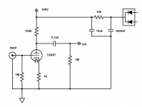
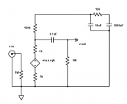
Here is a simple common cathode amplifier, and also its AC equivalent circuit.
The power supply is a simple CRC filter, fed by a rectifier.
Notice how the power supply is still part of the AC equivalent circuit. The rectifiers are gone
from the AC equivalent circuit because they only conduct briefly during a charging current pulse
from the power transformer, and do not affect the amplifier circuit's frequency response.
and without feedback. This is also the case for the Loesch article."
Here is a simple common cathode amplifier, and also its AC equivalent circuit.
The power supply is a simple CRC filter, fed by a rectifier.
Notice how the power supply is still part of the AC equivalent circuit. The rectifiers are gone
from the AC equivalent circuit because they only conduct briefly during a charging current pulse
from the power transformer, and do not affect the amplifier circuit's frequency response.
Attachments
Last edited:
i am a fan of using big caps in the psu, i made a 6LU8 pp power amp using 2 x 1000ufd/450 volts to filter out the plate b+ of the output stage.....
what have i learned? having a big cap in there is no guarantee of bag bass, it all boiled down to the OPT traffo itself more than anything else...
what have i learned? having a big cap in there is no guarantee of bag bass, it all boiled down to the OPT traffo itself more than anything else...
- Home
- Amplifiers
- Tubes / Valves
- How do you size a capacitor for a B+ node?