Small modification was made.
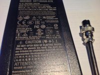
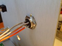
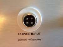
First was PSU jack change to another metal stif model.
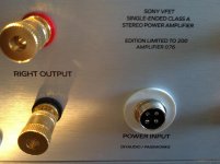
At the end of all work RCA inputs to FE card wire was cut short and resoldered.
And four Philips screws on back panel changed to torque version.
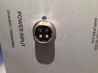
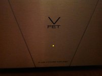
Et voila..ah with kit resistor yellow led is not bright but easy visible glow
First was PSU jack change to another metal stif model.
At the end of all work RCA inputs to FE card wire was cut short and resoldered.
And four Philips screws on back panel changed to torque version.
Et voila..ah with kit resistor yellow led is not bright but easy visible glow
Attachments
-
 15D32916-172A-42D8-BB93-ED9FD14EA6B3.jpg203.3 KB · Views: 482
 -
 4A31A703-878F-40C7-8342-EEC789C82A2B.jpg229.6 KB · Views: 457
 -
 8087FA7A-52AE-4C7B-AB99-42FB03C7DF27.jpg636.8 KB · Views: 447
 -
 4CA3CD13-BED0-4067-83BD-E01465D12E50.jpg424.2 KB · Views: 451
 -
 C43833DC-B9E2-4F68-829C-62818123FBAB.jpg273.5 KB · Views: 447
 -
 7C4D1ACC-710C-4AD3-A243-F314A9410EBA.jpg523.1 KB · Views: 226
 -
 3CD37A3D-169E-4E85-9629-9CE54E2E731F.jpg478.2 KB · Views: 217
 -
 AF7D5142-A768-4F19-A368-75A283467F3A.JPG129.4 KB · Views: 246
 -
 44285C0C-B533-4F88-9F0A-21E3B4126685.jpg535 KB · Views: 224
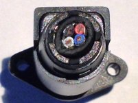
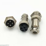
I use GX16 so is need be drilled for adequate diameter.
GX16/GX20/GX12 Aviation Plug Male&Female Wire Panel Metal Connector 2/3/4/5/6Pin | eBay
Red and blue wires are V+ pair.
Warning : make this modification at your own responsability
GX16/GX20/GX12 Aviation Plug Male&Female Wire Panel Metal Connector 2/3/4/5/6Pin | eBay
Red and blue wires are V+ pair.
Warning : make this modification at your own responsability
Attachments

Assume the pins are all isolated from the casing? I guess one would void the warranty on the PSU with this mod. Looks nice.
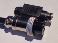
Yes 4 pins are isolated. Work great high quality connection.
Soldering wires is easy , the plastic material inside is hard like stone
and don't melt with high temperature.
Yes no more warranty on the PSU
Soldering wires is easy , the plastic material inside is hard like stone
and don't melt with high temperature.
Yes no more warranty on the PSU
Attachments

Spades connections for on-off switch are less large smaller onesattention
The quick-disconnects for the switch in my kit were too small as well. No biggie for me but future kits should address that.
Has anyone noticed the 1000uF 50V Nichicon caps with different font printing? I have 1 set that looks rather dubious and not the typical Nichicon font like in the other set:
https://i.imgur.com/fP96POX.jpg
https://i.imgur.com/fP96POX.jpg
I believe the shortness of the wires has been confirmed to be an error of calculations when building the kits.
I wonder if 6L6 or the store can share the cable part-number / model / type so that we can procure extra "matching" cable to help with our builds?
Thanks!
Rafa.
Yeah,
that would be nice. I'd like to give the amp the wiring look it deserves!
Although Teflon insulated wiring provided is some of the finest in the world, I personally find them a bit too stiff for direct soldered flying leads. The mechanical strain imposed by the solder wicked joint makes it very stiff and can potentially damage the trace/pad. Being a bit too short makes it even more difficult to use.
That’s one reason I went with high current silicone insulation “RC helicopter/car” battery/motor wiring. High temp insulation good for 200C, very flexible and supple, and it is easy to connect. It reduces mechanical strain that I encountered while trying to manipulate the board and panels to get assembled. Not having removable connectors on the PCBs makes installation and assembly a much trickier process requiring, what Soundhappy said, good advance planning, and a “dry check” fitment testing before final screws are applied.
Here is the type of wiring I am using. This 13ft x 5 color 18ga kit should allow you more than enough to build this amp: https://www.amazon.com/dp/B07G872J7V/ref=cm_sw_r_cp_api_glt_fabc_H8SDYCQEVHD0892AW4CA
For amp to speaker terminals and filter to amp PCBs... Dual strand (red and black) 16ga:
https://www.amazon.com/dp/B079CFZZYS/ref=cm_sw_r_cp_api_glt_fabc_DA9DHMSGP149FX4FG4YX
I totally see what you are saying but the wires work fine had they been a couple of inches longer here and there. There is something mindlessly relaxing about building a kit with all the parts included. I have never done that and I think it fits my current lifestyle and schedule. I was bummed out when I found the wires were not long enough, it kinda broke the 'Chi' of the process. 😉
Here is the soft start circuit that Jhofland developed to overcome the SMPS hiccup blues. It’s fairly simple and parts don’t cost much. I am going to modify it to be able to run from 36v. A low current 36v from the Mean Well supply can be switched as the remote enable. This will basically eliminate any arcing across the rocker switch which now controls maybe 10mA vs 3.2A. The current from the SMPS is initially passed through a 30ohm NTC. This slows the current enough to avoid tripping the hiccup behavior. The caps get slowly charged over say 2-5 seconds. After a set time (adjustable via RC constant), the low RDson mosfet conducts and bypasses the NTC, thereby fully switching the amp on. This slow charge will also hopefully, eliminate the speaker turn on thump. I think the size of the caps after the SMPS can be made much larger if desired.
Here is the board:
If it works I’ll post the Gerbers and BOM freely.
I'd rather pay you a couple of bucks for a PCB if you do a small batch of them. I have no time to chase down a PCB maker but I would very much like to address this thump with a simple bolt of solution. I am sure there are others that would take that up. BTW the image does not load for me.
Has anyone noticed the 1000uF 50V Nichicon caps with different font printing? I have 1 set that looks rather dubious and not the typical Nichicon font like in the other set:
https://i.imgur.com/fP96POX.jpg
Font printing of Nichicon in the kit was the same like the others Nichicon I bought recently from Mouser 🙂
Could be possible post image on the forum ? I don't see image with the link..
I'll add the image here (Hope it doesn't come out too large)

Left capacitors has the fonts i'm familiar with - Right is the one i'm questioning.
Left capacitors has the fonts i'm familiar with - Right is the one i'm questioning.
Hi, I don't have one of these myself, Just have my nose firmly pressed against the window following the builds and fingers crossed for the next lottery.
Regarding the leads being too short, They wouldn't be if the L bracket was placed central to the heatsink optimising heat distribution.
Andy
Regarding the leads being too short, They wouldn't be if the L bracket was placed central to the heatsink optimising heat distribution.
Andy
Left capacitors has the fonts i'm familiar with - Right is the one i'm questioning.
What is different ? Bigger point on the top of the " i " ?
Regarding the leads being too short, They wouldn't be if the L bracket was placed central to the heatsink optimising heat distribution.
Andy
Yes 🙂
Good news heatsinks after many hours are not very hot,
this chassis is OK for total of ~ 114 watts of heat dissipation
What is different ? Bigger point on the top of the " i " ?
The printing is in rather bold font. The dot above the "i" appears to be in diamond shaped. Click on the image to toggle in right aspect ratio. They're not the same.
@Super_BQ
Ah yes, I see better now.
Imo is nothing to be worried about if cap shape, size is the same and colour..
probably just printing machine ink consistency.
What you think?
Ah yes, I see better now.
Imo is nothing to be worried about if cap shape, size is the same and colour..
probably just printing machine ink consistency.
What you think?
Imo is nothing to be worried about if cap shape, size is the same and colour..
probably just printing machine ink consistency.
What you think?
I have no concerns. Just curious if others noticed the difference. It appears already, people have gone to more pricier capacitors but for myself, I want to keep everything as original as possible.
Long ago I recall there was a capacitor conspiracy where China had thought they copied a Nichicon's secret recipe forJust making capacitors which resulted in a high rate of capacitors failures globally (especially noted in PC motherboards). No one knew until everything was plagued.
Recently there's issue of fake Toshiba JFets and all that was to go by was the little differences in the printing. Not to mention, fake Sony VFets too.
@ Super_BQ
Yeah, I know.. but this is a different story..
I think Digi-Key and Mouser have long time commercial, professional contracts with official capacitors factories
they don't deal with " funny guys "
they care about reputation and are subscribed ont list of the official electronic components distributors
with adequate international laws regulations. Counterfeit electronic components - Wikipedia
I'd rather pay you a couple of bucks for a PCB if you do a small batch of them. I have no time to chase down a PCB maker but I would very much like to address this thump with a simple bolt of solution. I am sure there are others that would take that up. BTW the image does not load for me.
I’ll post the Gerbers and anyone can make or organize their own GB as I don’t have the time for that. I have tested the circuit, now modified for 36v operation. Works well with a 6 second delay using a 1M resistor on the RC timer with two 10uF 25v X7R capacitors in series to achieve 5uF and 50v.
I have to correct a mistake I made in saying that the circuit would use the switch to switch a low current flow. It would indeed still switch the main current flow, but upon contact, there would be a 30ohm NTC in series to significantly reduce the arcing, and hopefully, also reduce the speaker turn on thump. It would also allow for significantly larger electrolytic rail caps on the board of one wanted to do that and avoid the SMPS from going into hiccup mode.
Last edited:
- Home
- Amplifiers
- Pass Labs
- DIY Sony VFET Builders thread