How much external capacitance can MeanWell SMPS drive without "hiccup"?
Has anybody experimented with their MeanWell GST160A36 power supply, to find out how much capacitance you can connect to it without entering the dreaded Hiccup Mode at power-on? Some vendors provide a max CLoad specification on their datasheet but it appears MeanWell did not.
Has anybody experimented with their MeanWell GST160A36 power supply, to find out how much capacitance you can connect to it without entering the dreaded Hiccup Mode at power-on? Some vendors provide a max CLoad specification on their datasheet but it appears MeanWell did not.
on my mw rs-150-24 24v I have put a 10.000uf ,but I dont remember if with resistor in between ,2007....
Last edited:
I haven’t loaded my GST160A36 directly with any more than 3000 uF yet. That includes the 1000 uF on the filter board. I’ve seen 5000 uF specified on some enclosed chassis mount models, LRS, if I remember correctly.
More photos..Today at the evening with friend we organized music session 
Attachments
-
 AF89E759-5F07-4204-90BA-8AEAF39A44B5.jpg470.1 KB · Views: 507
 -
 13A05FDC-7C21-421A-9D08-D2A87EC7B9E2.jpg283.8 KB · Views: 499
 -
 D28D285A-9DEF-46B3-8811-3C2557B5CFDB.jpg315.9 KB · Views: 496
 -
 8B46B218-53C6-433C-872A-402C436E28D5.jpg449.4 KB · Views: 499
 -
 1622F7FE-B031-4F05-949E-14ED5A56A624.jpg418.4 KB · Views: 496
 -
 0BDCEF24-FB87-40E1-8160-9690FDAF5B3A.jpg472.7 KB · Views: 283
This might have been asked before, I would need to go to the workshop (I'll do anyway later today) to check, but has anyone tried what the turn off thump is like when switching the AC side of the meanwell off ?
I'll try and revert if noone has done that before, but that would suprise me, the topic has been discussed for various SMPS applications before...
I'll try and revert if noone has done that before, but that would suprise me, the topic has been discussed for various SMPS applications before...
Coolnose and Diyers
Thump is little less if disconected on AC side
but tiny difference with switch turn off
anyways I keep this amp without speakers protection card etc.
It's so little I am no worry about my full range drivers.
The same thing with filter psu , this amp is totally quiet,
no reason to build another filter for silence filtering 😉
Mr. Pass circuit design are perfect and work fantastic
Hi Mark,
Sadly not with "that" MeanWell power supply but, perhaps as a very rough guideline, we recently played around caps increasing with 2 other MW (and some chinese units)...
- LRS-200-36, obviously not the same product sadly, but with 36V and 5.9A the closest I have tried on a power amp. Copes daily with 6000uF on many many Class D builds, even 9000uF on some. Cheap chinese 36V / 5A sealed units (say cheap equivalent to the VFET PS) seem to do so on many Aiyima 04 amps with 6000uF (or more), including one I know very well that is used / started (on / off) on a daily basis...
-LRS-350-24 (24V, 14.6A), played personaly a lot with that one to replace 2 of the above as I didn't need full voltage, copes since last year daily with 18000uF, survived a couple of tests with 24000uF without any problem.
Of course the way the circuits load the caps may differ etc., but it could well be that even 3000uF is still conservative and double that still doable.
Sadly only first hand experience on that specific reference can tell though...
I hope this helps somewhat
Claude
Back then, I don't remember seeing in the MW LRS series documentation any indication of a max additional capacitive load, sadly...
I don't know if all the Meanwells offer current limiting, but my ones, older USP-225 24V and 48V certainly do at about 120% of their maximum current spec and they accept over 30000uF. They automatically shut off with obvious short circuit, so there should be some limit.
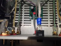
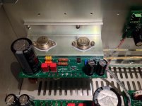
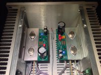
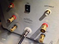
More photos..Today at the evening with friend we organized music session
Very nice, and probably the cleanest build I've seen so far. I am still building, but don't think I will come this clean.. It is surely inspiring 🙂
Tell more about how it sounds, it is so nice to read while I am in the process.
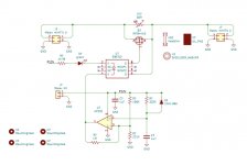
Here is the soft start circuit that Jhofland developed to overcome the SMPS hiccup blues. It’s fairly simple and parts don’t cost much. I am going to modify it to be able to run from 36v. A low current 36v from the Mean Well supply can be switched as the remote enable. This will basically eliminate any arcing across the rocker switch which now controls maybe 10mA vs 3.2A. The current from the SMPS is initially passed through a 30ohm NTC. This slows the current enough to avoid tripping the hiccup behavior. The caps get slowly charged over say 2-5 seconds. After a set time (adjustable via RC constant), the low RDson mosfet conducts and bypasses the NTC, thereby fully switching the amp on. This slow charge will also hopefully, eliminate the speaker turn on thump. I think the size of the caps after the SMPS can be made much larger if desired.

Here is the board:

If it works I’ll post the Gerbers and BOM freely.
Here is the board:
If it works I’ll post the Gerbers and BOM freely.
Attachments
Last edited:
Might want to use the low profile, flush with PCB, heatsinks that are deployed on the ACP+. There isn't a lot of maneuvering room inside a VFET chassis.
{second paragraph removed, this is not an output muting circuit! oops}
{second paragraph removed, this is not an output muting circuit! oops}
Last edited:
I don’t think a heatsink is needed here. RDson is 7mOhm x 3.4A is 24mW on a TO220 is nothing. It could be mounted on the floor next to the filter or on the back wall.
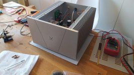
Finally the components was delivered yesterday!
Really horrible lack of information from both DHL and PostNord (Swedish local delivery) delivery was stuck at two places and when I finally got information to go pick it up it wasn't there and I had to come back the next day. But that's all forgotten now. 😀
The build was super nice. I love the thick cables included. Super easy to work with using a really sharp knife. The only complaint is that some of them was too short and I had to rotate and move one of the input boards closer to the back, and the cable for connecting the speaker jack's was just long enough. Yeah, and the chassis are always tricky to put together when everything is in the chassis. Using Philips screws are also a really bad choice but I guess I could buy other screws, but yeah.
I'm trying the amplifier in my main room ,70 m2, using modified JBL L19 (low efficiency) with a B1 for preamp. I might have to use most of the potentiometer but it has no problem with the listening volumes I listen to. And it sounds really nice too (suprised? No 🙂 )
Thanks all who made this happened!
Attachments
Last edited:
@ Diyers
This amp was built with a friend who is the final owner.
I help with soldering, continuity tests and made all internal wiring and bias adjustment.
Some observations about work organization.
First step:maybe chassis is less perfect, so better try first assembling all
and eventually drill or make aluminium more flat.
With the pcbs and wires inside, they are tricky or very difficult to do.. and avoid scream is too late now..
Next step: internal wiring need to be planify in advance as well
if not quickly you will find this good quality thick orange green wire is too short.
Keep wires at the distance from the audio inputs signal transformers.
Spades connections for on-off switch are less large smaller ones attention
Screws work ask for patience..
All other build steps are easy , bias test etc.
Was good time " Vfet amp camp " Thanks again :^ ) Cheers
This amp was built with a friend who is the final owner.
I help with soldering, continuity tests and made all internal wiring and bias adjustment.
Some observations about work organization.
First step:maybe chassis is less perfect, so better try first assembling all
and eventually drill or make aluminium more flat.
With the pcbs and wires inside, they are tricky or very difficult to do.. and avoid scream is too late now..
Next step: internal wiring need to be planify in advance as well
if not quickly you will find this good quality thick orange green wire is too short.
Keep wires at the distance from the audio inputs signal transformers.
Spades connections for on-off switch are less large smaller ones
attentionScrews work ask for patience..
All other build steps are easy , bias test etc.
Was good time " Vfet amp camp " Thanks again :^ ) Cheers
I believe the shortness of the wires has been confirmed to be an error of calculations when building the kits.
I wonder if 6L6 or the store can share the cable part-number / model / type so that we can procure extra "matching" cable to help with our builds?
Thanks!
Rafa.
I wonder if 6L6 or the store can share the cable part-number / model / type so that we can procure extra "matching" cable to help with our builds?
Thanks!
Rafa.
Tell more about how it sounds, it is so nice to read while I am in the process.
Its sound extraordinary specialy on the music with acoustic instruments, voices are beautiful as well
Tested with RME Fireface high quality audio card, this one have a lots of gain so music was plenty loud at 25% of the volume.
Feeling of acoustic space around the musicians, subtile sound nuances little vibratos are there, narrative music flow
can surprise even experienced audiophiles 😀 Have a nice day
..And it sounds really nice too (suprised? No 🙂 )
Excellent Vemsom
Congratulations


I believe the shortness of the wires has been confirmed to be an error of calculations when building the kits.
I wonder if 6L6 or the store can share the cable part-number / model / type so that we can procure extra "matching" cable to help with our builds?
Thanks!
Rafa.
Although Teflon insulated wiring provided is some of the finest in the world, I personally find them a bit too stiff for direct soldered flying leads. The mechanical strain imposed by the solder wicked joint makes it very stiff and can potentially damage the trace/pad. Being a bit too short makes it even more difficult to use.
That’s one reason I went with high current silicone insulation “RC helicopter/car” battery/motor wiring. High temp insulation good for 200C, very flexible and supple, and it is easy to connect. It reduces mechanical strain that I encountered while trying to manipulate the board and panels to get assembled. Not having removable connectors on the PCBs makes installation and assembly a much trickier process requiring, what Soundhappy said, good advance planning, and a “dry check” fitment testing before final screws are applied.
Here is the type of wiring I am using. This 13ft x 5 color 18ga kit should allow you more than enough to build this amp: https://www.amazon.com/dp/B07G872J7V/ref=cm_sw_r_cp_api_glt_fabc_H8SDYCQEVHD0892AW4CA
For amp to speaker terminals and filter to amp PCBs... Dual strand (red and black) 16ga:
https://www.amazon.com/dp/B079CFZZYS/ref=cm_sw_r_cp_api_glt_fabc_DA9DHMSGP149FX4FG4YX
Very nice, and probably the cleanest build I've seen so far. I am still building, but don't think I will come this clean.. It is surely inspiring 🙂
Thanks for kind words 😀
After batch 3 be relased I want build another Vfet SE for my self.
So I can make it hope more "perfect" or better..
Wish You have a good time on the work bench.
- Home
- Amplifiers
- Pass Labs
- DIY Sony VFET Builders thread