If you look at my wiring, I have done the same. I always do this, even with my KSA50.
Nice, well done -> (post #6323)

Extreme_Boky,
Yes, this is something I have seen Tom C (of Neurochrome) advise and as such I do this to all my amplifier builds. The primary reason is as you state, lower distortion.
Best,
Anand.
Yes, this is something I have seen Tom C (of Neurochrome) advise and as such I do this to all my amplifier builds. The primary reason is as you state, lower distortion.
Best,
Anand.
Last edited:
I remember now that not all designers agree on where the speaker return should be connected, for various reasons.
See pgs 7-9 on Bonsai’s primer here:
http://hifisonix.com/wordpress/wp-c...B-Design-Guidlines-for-Minimizing-Hum-1-1.pdf
Best,
Anand.
See pgs 7-9 on Bonsai’s primer here:
http://hifisonix.com/wordpress/wp-c...B-Design-Guidlines-for-Minimizing-Hum-1-1.pdf
Best,
Anand.
If it wasn't for the R2 (and the LED's which are not necessary at all, for the normal amplifier operation), the amp PCB's could do without ever needing to see the common reference point...
There's no localized decoupling on the AMP PCB's. With the short and thick wiring (good to couple that HF noise the white paper is talking about...but I question the amount of that (eventual HF) noise...), I see no reason why the speaker return should go to the AMP PCB's first.
I think, for what we have at the moment (no local decoupling, Zener D1 referenced of the Vee instead of common ground potential - Nelson at his best???), feeding the speaker return straight to PS common is a better option.
Last edited:
I’m definitely going to try both ways. In my build I am using a pair of SLB supplies which are mounted on my front panel, as such the speaker return wiring can get a bit long!
My primary wiring is dead center, minimizing any hum issues hopefully. Toroidy 800VA encapsulated.
Thanks for the input/advice.
Best,
Anand.
My primary wiring is dead center, minimizing any hum issues hopefully. Toroidy 800VA encapsulated.
Thanks for the input/advice.
Best,
Anand.
So beautiful!!!! 😎
View attachment 946575
View attachment 946576
View attachment 946577
Many many thanks to ZM & 6L6!
I'll post my progress step by step
Boards look great in black! Look forward to hearing your thoughts!
Beautiful indeed!
I see that J1 and J2 do not face each other in this version. So there's no need for them to keep each other in a warm hug. Right?
no need
show me Papa's pcb with JFets hugging
I am obsessed, but even that less with years
🙂
I'm collecting all the components..
Cool...waiting for sound review. Nice job Z!
Boky....good info...keep those wires short.
name of the game with this pcb was simplicity, maximal, in everything (preparing, assembly, setting), without loosing performance
among other things, there is Ground Braking Resistor, for Greedy Boyz having difficulties with proper wiring
I don't need it in my builds, but better to have it, just in case
all details when 6L6 choose to publish it, it's outa my hands
So does routing the speaker return to the power supply gnd. improve sound quality or just reduce the possibility of ground loops or hummm.
I can not tell if you wired inputs as RCA's, or XLR's...
XLR (balanced topology) and Aleph J go together like a baby bum and the potty. You will not need any ground-lift resistors. My Aleph J is absolutely, totally dead-quiet. Zero hum/buzz. Beautiful!
Can I ask- where do you ground the XLRs? To the chassis or via the amp board ground? Thanks
Can I ask- where do you ground the XLRs? To the chassis or via the amp board ground? Thanks
I grounded mine on audio ground on the amp board.
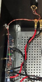
The XLR shield goes to its designation on the AMP PCB. I used a slight twist of + and - input signal wires and included the shield bare litz (multi-strand) wire in that twist as well. The ground-lift resistor must be removed (if previously used with RCA's, i.e. with amp wired to accept the single-ended input, which was how I used the amp initially).
It is important that the shield (bare) wire does not touch the chassis; the chassis and the amplifier ground are separated by the CL60, which in this case provides a 10 ohms difference between these two potentials.
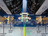
The speaker negative (return) should not go to the amp PCB -> it should go to the power supply PCB. The power supply PCB does not really have a ground segregation provision(s); the best you could do is to look at the second photo I attached. I used the X4 ground connection on the PS PCB for an additional decoupling capacitor....; however, the X4 (visible on the photo, only just <- left-hand side) is an even better point to return the signal ground from the AMP PCB.
NOTE: The first photo is an old photo - it shows the speaker return going back to the AMP PCB...
Aleph J needs two power supplies; using the separate power supplies will bring an additional level of benefits to its separation of sound (the perceived left-right, and top-bottom extension).
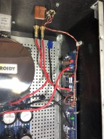
Edit: The latest photo attached.
It is important that the shield (bare) wire does not touch the chassis; the chassis and the amplifier ground are separated by the CL60, which in this case provides a 10 ohms difference between these two potentials.
The speaker negative (return) should not go to the amp PCB -> it should go to the power supply PCB. The power supply PCB does not really have a ground segregation provision(s); the best you could do is to look at the second photo I attached. I used the X4 ground connection on the PS PCB for an additional decoupling capacitor....; however, the X4 (visible on the photo, only just <- left-hand side) is an even better point to return the signal ground from the AMP PCB.
NOTE: The first photo is an old photo - it shows the speaker return going back to the AMP PCB...
Aleph J needs two power supplies; using the separate power supplies will bring an additional level of benefits to its separation of sound (the perceived left-right, and top-bottom extension).
Edit: The latest photo attached.
Attachments
Last edited:
Aleph J needs two power supplies; using the separate power supplies will bring an additional level of benefits to its separation of sound (the perceived left-right, and top-bottom extension).
I find my Aleph J with dual supplies is stunning.
With the things I picked up along the way, I am gearing up to build a fresh Aleph J; this time with a "discrete" power supply & correct returns for the XLR inputs, R2 resistors, speakers, and connection to chassis. I will not use the LED's on the amp PCBs, so that R2 resistor return will indeed be only for R2. No short circuit protection, C1 bypassed.
I think Nelson used a single LED across the power supply rails, so no return currents to PS common was required 🙂
Dual transformers & power supply, or {2x24V} x 2 SMPS from Meanwell.... still testing this one...
I think Nelson used a single LED across the power supply rails, so no return currents to PS common was required 🙂
Dual transformers & power supply, or {2x24V} x 2 SMPS from Meanwell.... still testing this one...
Some follow up:
1. You use a bare wire for the ground from the XLR to the Amp board? Any reason it can't be insulated? Esp since you caution not to let it touch the chassis (BTW, I measured a 13ohm diff. between the amp ground and the chassis ground).
I currently use RCAs, with the Neg input and Ground shorted (connected to each other) at the amp board, so it seems electrically this will be equivalent? I've done most of all the basics to eliminate hum (twisted leads, mains under the floor for instance), but still have it slightly. I notice the slight hum is related to the input leads- unconnected it gets louder when I touch them- some sort of capacitance thing.
2. In your middle photo- you're connecting a line from those ties between the 2 PSU boards to the CL60? That's better than connecting one of the grounds on one of the PSU boards to the CL60? So just solder the green line to the middle of a tie or something?
3. On your right photo, curious about the capacitor you have on the XLR on your right photo?
Thanks so much!
The XLR shield goes to its designation on the AMP PCB. I used a slight twist of + and - input signal wires and included the shield bare litz (multi-strand) wire in that twist as well. The ground-lift resistor must be removed (if previously used with RCA's, i.e. with amp wired to accept the single-ended input, which was how I used the amp initially).
It is important that the shield (bare) wire does not touch the chassis; the chassis and the amplifier ground are separated by the CL60, which in this case provides a 10 ohms difference between these two potentials.
The speaker negative (return) should not go to the amp PCB -> it should go to the power supply PCB. The power supply PCB does not really have a ground segregation provision(s); the best you could do is to look at the second photo I attached. I used the X4 ground connection on the PS PCB for an additional decoupling capacitor....; however, the X4 (visible on the photo, only just <- left-hand side) is an even better point to return the signal ground from the AMP PCB.
NOTE: The first photo is an old photo - it shows the speaker return going back to the AMP PCB...
Aleph J needs two power supplies; using the separate power supplies will bring an additional level of benefits to its separation of sound (the perceived left-right, and top-bottom extension).
Edit: The latest photo attached.
- Home
- Amplifiers
- Pass Labs
- Aleph J illustrated build guide