I don't think you will find this pcb useful for hiraga. your bridge will be too hot, what about heatsinking. best to use chassis mount types...
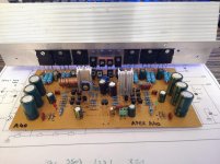
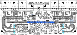
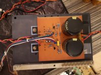
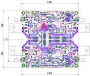
caps appear to be 25 mm dia on pcb, would your caps fit?
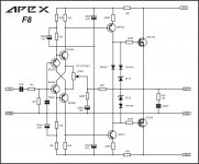
r1/r2 can be 0.33 or 0.22 5W, r3/r4 can be 470 to 560 2W-3W
caps appear to be 25 mm dia on pcb, would your caps fit?
r1/r2 can be 0.33 or 0.22 5W, r3/r4 can be 470 to 560 2W-3W
Hi Prasi
Thank you for your help.
Cap s 22000uf 16v fits perfectly. What should be the value of the R6 and R7 resistors.
I will solder the bridge diodes under the pcb board and connect it with the case.
Thank you for your help.
Cap s 22000uf 16v fits perfectly. What should be the value of the R6 and R7 resistors.
I will solder the bridge diodes under the pcb board and connect it with the case.
a40 second channel
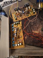
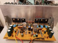
Apex A40 second channel finished and singing, it is amazing in stereo 🙂. I need to add third pair of output transitor on my first channel and change the output coil to adequate one. Almost finished Apex Psu 15 too. 🙂
Apex A40 second channel finished and singing, it is amazing in stereo 🙂. I need to add third pair of output transitor on my first channel and change the output coil to adequate one. Almost finished Apex Psu 15 too. 🙂
Attachments
APEX AX20P (AX14-TEF)
AX20P is,as it is already known actually AX14-TEF,but on steroids because of three output transistor pairs (at least this one by me). it needs replacing 1k resistors in bias-circuit to 1k5 or 1k8 (related to schematics) to achieve bias adjusting. with 1k bias is constantly 0mA (or 0mV at emiter resistor).
HomeMadeAudioProject: APEX AX20P (AX14-TEF) - YouTube
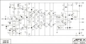
100W Ultimate Fidelity Amplifier
APEX AX20r,stil under testing. needs a little bit adjustment but it promises:
YouTube
Is this layout different from last your ax20 xl layout?...to be: AX11 XXXL and AX20 XL:
i could post it only in pdf,lay6 can not be posted here,and i have not rad or zip option on my pc.
Thanks,pdf is ok🙂
here it is:
Attachments

member David offered to make a zip/rar file with all those and lay6 file in it. when i get it from him,i will post it here. he is also wellcome to do it by him self. 🙂
a40 update
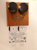
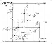
Big heatsink arrived for the second channel, third pair of output transistors mounted on the first channel and PSU 15 finished and tested 🙂. Ac input +/- 38V gives 36V-52V at output with 12V zeners instead of 15V zeners. Plan for Psu 15 is to be in separated box and I will use it to power my various amplifiers. Now I have to prepair some nice box for A40, maybe I will make TB3 tone control too and pack it with A40.
Big heatsink arrived for the second channel, third pair of output transistors mounted on the first channel and PSU 15 finished and tested 🙂. Ac input +/- 38V gives 36V-52V at output with 12V zeners instead of 15V zeners. Plan for Psu 15 is to be in separated box and I will use it to power my various amplifiers. Now I have to prepair some nice box for A40, maybe I will make TB3 tone control too and pack it with A40.
Attachments

member David offered to make a zip/rar file with all those and lay6 file in it. when i get it from him,i will post it here. he is also wellcome to do it by him self. 🙂
all in one:
Attachments
- Home
- Amplifiers
- Solid State
- 100W Ultimate Fidelity Amplifier