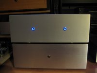
Chassis #104 just arrived.
I was concerned that my planned front panel button might be too large, but I think it's going to work out nicely...
I think it looks good!
I'll be doing the same on mine, when I win next round. 😉
If you look on the back side of the front panel, mine had three holes in a line, the center hole for the LED.
You hit one of those with a hole saw and you may end up with a larger than you wanted oval hole.
With out a milling machine, a 1" hole is.......
Hmm, I hadn't noticed those little holes on the inside.
OK... anyone near San Jose / Mountain View with a milling machine willing to help me out? 😀
hifiZen,
IMHO stay away from a hole saw for this particular project.
In my experience a good quality forstner bits, a drill press, some cutting fluid and a patient approach can give good results.
If you can find someone with expertise and a proper setup (e.g. milling machine), nothing like it.
IMHO stay away from a hole saw for this particular project.
In my experience a good quality forstner bits, a drill press, some cutting fluid and a patient approach can give good results.
If you can find someone with expertise and a proper setup (e.g. milling machine), nothing like it.
You could try...start with a small pilot hole ... then multiple steps increasing drill bit sizes to say 1/2. Then step bit to size. Go slow...and he gentle.
I think it looks good!
I'll be doing the same on mine, when I win next round. 😉
Excellent! I'll be sure to post any hole-drilling learnings.
Chassis work is always the hardest part of a project, I find.
For anyone who's curious, that particular switch is Mouser p/n 506-AV2511E312Q04.
Red illuminated ring (which I prefer vs. blue, being more subtle with the lights dimmed watching a movie). It is a push-push on/off, latching in a slightly recessed position (including the illuminated ring, which moves with the button) when ON, then returning to a flush position when OFF (actually, there are both NC and NO contacts, so I suppose you could reverse that if so desired).
Note - this switch has only a 3A rating - a little undersized to use with the external DC power brick / directly in place of the kit switch. My plan is to retrofit a filtered IEC receptacle on the rear panel and install an internal SMPS, in which case the 3A rating should suffice.
There are a number of similar switches out there, including ones from Bulgin and EAO.
hifiZen,
IMHO stay away from a hole saw for this particular project.
In my experience a good quality forstner bits, a drill press, some cutting fluid and a patient approach can give good results.
If you can find someone with expertise and a proper setup (e.g. milling machine), nothing like it.
Forstner bits in aluminum!?! OK, I wouldn't have personally given that approach more than passing consideration... I can envision the pointy circumference tips cutting well, but my imagination is having problems when the main cutting width of the blades reach the flat surface and start cutting wide chips. But I haven't ever tried it, so it's interesting to hear from someone that it can indeed work.
But I think you're right... this project isn't one to experiment on, at least until a confident approach is established. I think I'll try out the hole saw on some scrap 1/4" aluminum stock first and just see how it behaves.
I've used milling machines plenty before, and they are indeed the obvious way to go, if you really want to do it right.
A stepped drill bit in a drill press would work. Use cutting fluid and drill a little at a time to allow the bit to cool off.
I'm guessing the teeth on a hole saw will fill up pretty quick in thick aluminium....and then the heat starts. Forstner bit has to remove a LOT of material at once....again heat. My gut tells me not to use those methods. I am really wishing for great outcomes for you all. Keep us updated..
I have drilled holes in 8mm front plates a few times with a stepped drill bit and hand held drill. I taped the outside face to protect the finish. I used a centre punch to mark the hole, drilled a small diameter guide hole, and then drilled the final hole with the stepped drill bit. With a thick front plate, drilling from both sides is required.
It's a bit scary with no room for mistakes so stop and check often to make sure that you do not over-drill the hole (too large diameter).
My hand drilled front panels:
It's a bit scary with no room for mistakes so stop and check often to make sure that you do not over-drill the hole (too large diameter).
My hand drilled front panels:
Attachments
Last edited:
Does VFET like a pair of AK6?
Let us know if that upper mid peak imposes itself.
dave
... and part of my reason for posting was specifically to solicit some feedback. So thanks - I do appreciate your opinion. Don't want to do something irreversible that I might regret later.
Build it stock first and see if you really truly want the switch on the front. The top switch is very easy to find and operate by feel.
BTW I wish the kit had just a little bit more green/orange -- speaker wire. Miscalculated a bit now will have to improvise or use not matching wire 🙂
It's upright in the guide because some of the Mark Johnson front-ends are significantly bigger and will need to be mounted as shown if anybody wants to use them...
If you ever want to swap know that the orientation may need to change. Easy enough... this is DIY after all!!
It wasn't you that miscalculated... I did. The first batch of the completion kits are shy a little wire because apparently I can't do basic addition... 🙁 The 2nd batch have an additional 2' of one of the colors, there should be enough to finish the job, even if the color code won't hold for the entire thing...
If you ever want to swap know that the orientation may need to change. Easy enough... this is DIY after all!!
BTW I wish the kit had just a little bit more green/orange -- speaker wire. Miscalculated a bit now will have to improvise or use not matching wire 🙂
It wasn't you that miscalculated... I did. The first batch of the completion kits are shy a little wire because apparently I can't do basic addition... 🙁 The 2nd batch have an additional 2' of one of the colors, there should be enough to finish the job, even if the color code won't hold for the entire thing...
Last edited:
Was expecting to see more impressions by now, but alas, they must've been lured in -- like the voice of a siren. 😀
Can't wait to get a VFET up and running.
Can't wait to get a VFET up and running.

It wasn't you that miscalculated... I did. The first batch of the completion kits are shy a little wire because apparently I can't do basic addition... 🙁 The 2nd batch have an additional 2' of one of the colors, there should be enough to finish the job, even if the color code won't hold for the entire thing...
Not a big deal. Found very similar wire in my wire pile...
So you connect o- (orange) to the streaker + so you do not have to reverse actual speaker cable? Isn't it better to wire actual ground to the speaker "-" and then deal with the speaker wire? Just conventional sense tells me + is a signal and - is ground in SE amp...
- Home
- Amplifiers
- Pass Labs
- DIY Sony VFET Builders thread