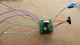
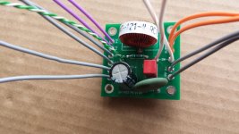
A quick ohmeter check between the -ve terminal(s) and the chassis with the Meanwell plugged in would verify this.
The MeanWells I have are like you wrote. The Ve- is connected to the shield.
Three of the six front-end cards have JFET input, and the other three front-end cards do not. Have a look at Scourge and Bulwark for example.
I was about the NP one included with the Vfet kit, who have jfets buffer input.
I stay in tune on 5 others front-ends cards availability in the DiyAudio Store.
Thanks and kind regards 🙂
Kit arrived in Hong Kong
My kit arrived too, all the way to Hong Kong. So excited.

My kit arrived too, all the way to Hong Kong. So excited.
Last edited by a moderator:


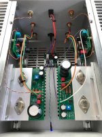
Finally got everything wired up. Minor mishap w/ the tab on the binding post snapping off while trying to push the spade connector on. I jerry rigged it for now and ordered another. Otherwise...easy peasy. Although I will say that this is a tight squeeze for your hands (as everyone is saying). Mine aren't that large and it was a bit tricky at times.
Pots set halfway were at like 19.5 or so volts, so just a minor turn and I was at 20.00 on both channels. Seemed to hold steady.
As for the "screws too long for mounting the output boards", I just swapped some of the M3 screws that came with the chassis in place of the other ones and they worked a treat!
Only had a chance to listen briefly, but it's fantastic. Same family as it's big brother (the M2 that I use as my main amp), but maybe a bit more detailed? We'll see over time.
The best part is that it's plenty of juice for my Harbeths in the living room. They're 6ohm (but pretty benign) and only 86db. As loud as I would ever generally listen the volume was most of the way up (maybe 90-95%). But that's with a Quad 34 that only puts out 1.6V. So with a proper preamp (in my situation), you could probably boogie a bit with this thing too.
Another fantastic project. Thanks Nelson for the design and devices and DiyAudio for the kit!
PS. The left rear panel is now properly aligned and flush. Didn't realize until after viewing this pic 😀
Attachments
Last edited:
BTW, the devices are pretty hot (can barely touch them for a second or two). The brackets are warm but I can keep my finger on it for a while. The heatsinks are just a bit warm. My temp probe broke, so I can't get numbers for now. Seems like this is how things are supposed to be though...
Lookin' good! By chance, would you have the part number or link for those binding posts? I like them and thought about using them in another amp.
one can do majority of wiring with heatsinks still laying aside
some cardboard pieces as scratching protection and that's it
some cardboard pieces as scratching protection and that's it
btw, there ain´t no ipods anylonger ; )
What's an ipod? I'm still using my Zune when I travel (which means not much since Covid started...)
Lookin' good! By chance, would you have the part number or link for those binding posts? I like them and thought about using them in another amp.
Thanks! No dice on the binding posts though. I just contacted Elena at the DiyAudio store. She says they're available from the store but on a quick look I couldn't find them. I'll let you know when I hear back (if I receive a link).
one can do majority of wiring with heatsinks still laying aside
some cardboard pieces as scratching protection and that's it
Yup, did that. The tricky part was getting hands and tools inside to attach all the panels together!
Thanks for the report! That setup seems great! Really envious of your Harbeths!
Can I ask how exactly did the post break? What did you do that we should avoid? I am trying to avoid every possible error, as they would be really expensive and time-consuming when I start my build. Sorry you are the guinea pig that figured out the hard way. Thanks for sharing!
Rafa.
Can I ask how exactly did the post break? What did you do that we should avoid? I am trying to avoid every possible error, as they would be really expensive and time-consuming when I start my build. Sorry you are the guinea pig that figured out the hard way. Thanks for sharing!
Rafa.

Thanks for the report! That setup seems great! Really envious of your Harbeths!
Can I ask how exactly did the post break? What did you do that we should avoid? I am trying to avoid every possible error, as they would be really expensive and time-consuming when I start my build. Sorry you are the guinea pig that figured out the hard way. Thanks for sharing!
Rafa.
Rafa, the spade(male) part of the panel connector snapped off when he was trying to plug in the female quick connect wire connector to it. Those female ends can be tight so it may be advisable to gently try plugging it in and if there is a lot of resistance you may want to slip an appropriate size flat blade screwdriver into the female connector to gently widen it.I stress gently or else it will open too much in which case you would have to squeeze it and try again.I've had to do just this with connectors when I replaced the tweeters in my speakers.
Thanks for the report! That setup seems great! Really envious of your Harbeths!
Can I ask how exactly did the post break? What did you do that we should avoid? I am trying to avoid every possible error, as they would be really expensive and time-consuming when I start my build. Sorry you are the guinea pig that figured out the hard way. Thanks for sharing!
Rafa.
Sure thing. Nothing out of the ordinary really...just pushed too hard, I guess. They are a bit snug to get on (as they should be), but this one really wasn't going. So I just pushed harder. Probably should have expanded the connector a bit with a screwdriver blade or something.
The Harbeths are C7ES2. If you can find a pair used...much cheaper than the current ones. I tried some series 3 and they were too bright for me. I have some large horn speakers that I built, but they have not been hauled out yet to demo with. They might not come out given how well this works w/ the lower efficiency speakers!
@enochROOT
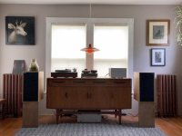
interesting speakerstands ; )
HEHEHE...they do look a bit like they're levitating. Makes me nervous seeing that angle sometimes 😉 Just a "T" cross section.
For those spade and crimp connections if you just ever so slightly (so slightly you cannot even visually see that you did anything) open the very front of the connector that slides onto the spade.... it will then slide on much easier but still retain the grip you need.
Who talks about WAF??
Meet Jill, her Klipschorns were too big for her house, so she bought a bigger house - YouTube
Does VFET like a pair of AK6?
Meet Jill, her Klipschorns were too big for her house, so she bought a bigger house - YouTube
Does VFET like a pair of AK6?
Kudos to that Jill
however, I know another Jill ....... she wasn't just working in ESS, but she was later working in Treshold and she took Papa under her wings.
Go figure ....... that is impossible to beat
🙂
however, I know another Jill ....... she wasn't just working in ESS, but she was later working in Treshold and she took Papa under her wings.
Go figure ....... that is impossible to beat
🙂
We need more "Jill's"?
Are those the famous K-horns? .....AK6?
Ladies & Gentlemen: The KLIPSCHORN! - YouTube
.......nice listening room......but he does not have a VFET amp.
How does these sound?
They are not very big and fits in the corners so most people should be able to have them.
Are those the famous K-horns? .....AK6?
Ladies & Gentlemen: The KLIPSCHORN! - YouTube
.......nice listening room......but he does not have a VFET amp.
How does these sound?
They are not very big and fits in the corners so most people should be able to have them.
- Home
- Amplifiers
- Pass Labs
- DIY Sony VFET Builders thread