I wrote that several times, here and probably in some other thread - ask woofertester for e-bay seller he bought from
as far as I remember, he found them genuine, with curve tracer
as far as I remember, he found them genuine, with curve tracer
I’m happy to organize a group buy for Papa’s Lu1014 supply. I’m waiting for his permission to set it up. Woofertester has agreed to match the devices.
Just curious, what will be the matching parameters (Vds, IA) to use (for a sane build 😀) ?
Vds => 15V-ish?
ID => 1A-ish?
Vds => 15V-ish?
ID => 1A-ish?
if you are asking for LU - no reason to match them differently than Pa did show on p9/10 of ZV9 article
https://www.firstwatt.com/pdf/art_zv9.pdf
https://www.firstwatt.com/pdf/art_zv9.pdf
rate of forgetting things already is greater than of things I'm learning
and I remember nothing

and I remember nothing
Just curious, what will be the matching parameters (Vds, IA) to use (for a sane build 😀) ?
Vds => 15V-ish?
ID => 1A-ish?
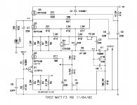
F3 schematic attached. It appears that the LU1014 lives at 2.4v Vds at 1.5A Ids. That will be where they are matched. While I am at it, I will measure Rds and DC transconductance at 1.5A. The measurements will be at room temperature for matching purposes. At operating temperature in your amp, the device behavior will likely be different. Hopefully the matching will remain. No guarantee. Should be much better than two random devices.
Attachments
I have LU1014D JFETs on order as per recommendations from Woofertester. When I receive them I am planning to experiment with a variety of heatsink attachment methods and stress test them relatively high currents, up to 10A or more. I am assuming that the heatsink temperature under the FET can be kept to below 55C. I haven't yet decided on the appropriate stress tests. Suggestions are welcome.
I have LU1014D JFETs on order as per recommendations from Woofertester. When I receive them I am planning to experiment with a variety of heatsink attachment methods and stress test them relatively high currents, up to 10A or more. I am assuming that the heatsink temperature under the FET can be kept to below 55C. I haven't yet decided on the appropriate stress tests. Suggestions are welcome.
Keep an eye on gate current. At 10A Ids, there may be significant gate current. If you are interested in that Ids current range, I can do some curve tracing there.
For Vds > 5V, I found that the curve tracer became unstable.
I do not expect idle current be be greater than 5A, probably less. The 10A figure was for maximum power output peak current.
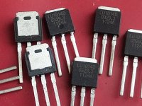
I bought some LU1014D on AliExpress.
They look refurbished, you can see that new legs have been attached.
Here's a trace I did for one LU1014D:
Vc from 0 to 20v, max 200ma (without heatsink)
Vb -0.8 to -1.6v in steps of 0.1v,
so each trace corresponds to a different Vb
What do you think, real enough ?
They look refurbished, you can see that new legs have been attached.
Here's a trace I did for one LU1014D:
Vc from 0 to 20v, max 200ma (without heatsink)
Vb -0.8 to -1.6v in steps of 0.1v,
so each trace corresponds to a different Vb
What do you think, real enough ?
Attachments

I bought some LU1014D on AliExpress.
They look refurbished, you can see that new legs have been attached.
Here's a trace I did for one LU1014D:
Vc from 0 to 20v, max 200ma (without heatsink)
Vb -0.8 to -1.6v in steps of 0.1v,
so each trace corresponds to a different Vb
What do you think, real enough ?
That is exactly what my cure tracer produces. You also have the wonkiness after 5V that I observed.
Last edited:
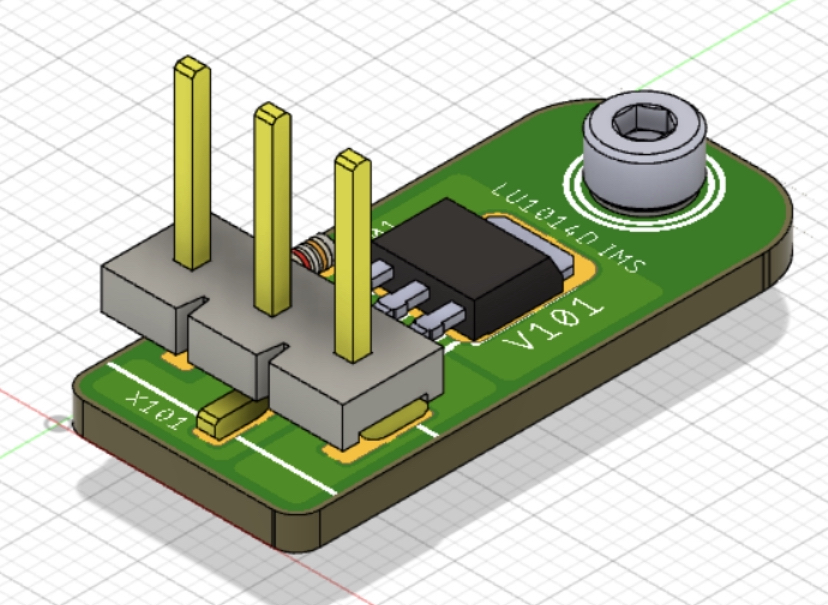
With ZM’s blessing, JPS64 and I have started working on a LuDEF with interchangeable input stages following M2X front end mechanical footprint. The M2X FE footprint will be the modified 5 bolt Yarra format that also contains a GND terminal as not all front ends are GND reference-free. We also have an aluminum PCB TO247 adapter board for the LU1014D. It should make mounting it with proper thermal contact much easier. The IMS PCB is 2mm thick and will provide a nice easy to use package and good thermal properties.
Last edited:
Is the Cascoding in LUDEF modulated like in the F3?
no, besides some wakoo effects Lu is getting in DEF arrangement - there is some Ugs action happening
With ZM’s blessing, JPS64 and I have started working on a LuDEF with interchangeable input stages following M2X front end mechanical footprint. The M2X FE footprint will be the modified 5 bolt Yarra format that also contains a GND terminal as not all front ends are GND reference-free. We also have an aluminum PCB TO247 adapter board for the LU1014D. It should make mounting it with proper thermal contact much easier. The IMS PCB is 2mm thick and will provide a nice easy to use package and good thermal properties.
adapter pcb is big enough, but screw position too far from center
making it wider (if shorter) and allowing for 2 side positioned screws?
Is the electrical insulation between the LU1014 and the adaptwr or between the adapter and the heatsink (preferred)? What is the means of attaching the LU1014 to the adapter?
- Home
- Amplifiers
- Pass Labs
- LuDEF