I believe we were talking about that when Marcel was exploring the phase plug being built into the WG
Was that the expansion part or the compression section? My understanding is that the phase plug mainly is used with the intention of forming a flat wave front at the throat. Wouldn’t compression be more related to the ratio of diaphragm area vs throat area?
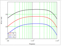
Here is a sim changing the diaphragm area while the plane wave tube remains constant. The compression ratio would be 4:1 down to almost 1:1.
This curve demonstrates why I say that most of a waveguide systems gain comes from the compression ratio and not anything having to do with the waveguide.
This curve demonstrates why I say that most of a waveguide systems gain comes from the compression ratio and not anything having to do with the waveguide.
Attachments
Last edited:
My understanding is that the phase plug mainly is used with the intention of forming a flat wave front at the throat. Wouldn't compression be more related to the ratio of diaphragm area vs throat area?
Pressure variation by the movement of the diaphragm leads to compression and rarefaction of air inside phase plug slots. The phase plug is basically an acoustic transformer that equalises path lengths and increases radiation efficiency when the combined slot area is smaller than the diaphragm area > compression ratio.
Last edited:
I was also wondering about compression ratio vs directivity at the higher frequency end.Here is a sim changing the diaphragm area while the plane wave tube remains constant. The compression ratio would be 4:1 down to almost 1:1.
This curve demonstrates why I say that most of a waveguide systems gain comes from the compression ratio and not anything having to do with the waveguide.
Yes, I was wondering whether modifying the diaphragm end of the phase plug for a more fluent transition while increasing the length if the phase plug would provide better performance. Currently lots of the drivers seems to not have a smooth transition between the converging side and the diverging side of the throat.Pressure variation by the movement of the diaphragm leads to compression and rarefaction of air inside phase plug slots. The phase plug is basically an acoustic transformer that equalises path lengths and increases radiation efficiency when the combined slot area is smaller than the diaphragm area > compression ratio.
I was also wondering about compression ratio vs directivity at the higher frequency end.
The compression ratio per se will not have an effect on the directivity, but how it is accomplished with the phase plug design will have some effect, although not a major one. The waveguide design has the dominate effect.
You might be thinking of the gap between the diaphragm and the phase plug as this does have a strong effect on HF output, but this is independent of the compression ratio.
Last edited:
I was wondering why not try to make the compression and expansion side of the throat kind of symmetric. That seems to be the major source of distortion. When symmetric, then I agree that directivity will not have any relation with compression ratio.
Here is a sim changing the diaphragm area while the plane wave tube remains constant. The compression ratio would be 4:1 down to almost 1:1.
This curve demonstrates why I say that most of a waveguide systems gain comes from the compression ratio and not anything having to do with the waveguide.
Very interesting!
I bought a couple of the BMS compression drivers that have a throat of 0.63", mostly because I like building small speakers.
But the more I use them, the more I like them, and one of the reasons is because their output level is kinda ridiculous.
http://www.bmsspeakers.com/fileadmin/bms-data/curves_compression/he_drivers/bms_4526he_curves.jpg
Over 110dB with one watt.
Of course, there are many compression drivers that are loud. But few are this inexpensive ($80) and this small (6cm in diameter.)
I hadn't considered that much of this may be due to the compression ratio, since the throat is quite small.
For comparison's sake, B&C's ring radiator is a little bit less efficient, a little bit larger and a little bit more expensive:
DE360 HF Drivers - B&C Speakers
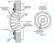
For example in the picture attached, the red lines point to abrupt change in cross section variation. Why not have smoother transition as shown as the green lines illustrate?I can't really comment since I have no idea what you are talking about.
Attachments
Earl, may I take the liberty to ask a question related to the picture in post 6712?
It has always struck me that CD diaphragms are relatively flat (for pseudo domes that is). That is understandable from the perspective of creating a flat wavefront with the help of the phase plug.
On the other hand since FEM analysis of cones and domes developed, it became known that a higher dome is far less susceptible to break up. See e.g. the Peter Larssen video's.
Would a higher dome have negative effects on wavefront forming, provided the phase plug would be redesigned accordingly?
I would expect the wave flow pathway to have a smoother cross section transition would have more desirable results.soongsc would it not be the other way around?
I have also been thinking along those lines. Actually, the final shape would not be a sphere.Earl, may I take the liberty to ask a question related to the picture in post 6712?
It has always struck me that CD diaphragms are relatively flat (for pseudo domes that is). That is understandable from the perspective of creating a flat wavefront with the help of the phase plug.
On the other hand since FEM analysis of cones and domes developed, it became known that a higher dome is far less susceptible to break up. See e.g. the Peter Larssen video's.
Would a higher dome have negative effects on wavefront forming, provided the phase plug would be redesigned accordingly?
For example in the picture attached, the red lines point to abrupt change in cross section variation. Why not have smoother transition as shown as the green lines illustrate?
I had this concern many years back - that the sharp corners would create turbulence and degrade the sound. But testing this showed it to be insignificant. Making the radius on the inner gap larger increases the volume in front of the diaphragm - composed of the area times the gap. This volume is a LP filter and acts to lower HF response as it gets larger. Hence, your idea would not do much more than lower the HF response.
Earl, may I take the liberty to ask a question related to the picture in post 6712?
It has always struck me that CD diaphragms are relatively flat (for pseudo domes that is). That is understandable from the perspective of creating a flat wavefront with the help of the phase plug.
Yes, deeper domes are more rigid, but there is a downside in compression drivers. The deeper dome will create greater standing wave levels in the gap area (see discussion here many pages back) which are undesirable. Hence there is an optimum depth and I suspect that it is just about where the current diaphragms lie.
Interesting point, seems like experiment to do if there are no published data and reports. Less slots would also reduce volume. But I guess a smoother throat transition between the compression and expansion side would be a plus.I had this concern many years back - that the sharp corners would create turbulence and degrade the sound. But testing this showed it to be insignificant. Making the radius on the inner gap larger increases the volume in front of the diaphragm - composed of the area times the gap. This volume is a LP filter and acts to lower HF response as it gets larger. Hence, your idea would not do much more than lower the HF response.
I guess this is assuming the phase plug height does not change?Yes, deeper domes are more rigid, but there is a downside in compression drivers. The deeper dome will create greater standing wave levels in the gap area (see discussion here many pages back) which are undesirable. Hence there is an optimum depth and I suspect that it is just about where the current diaphragms lie.
Less slots would also reduce volume.
I guess this is assuming the phase plug height does not change?
Less slots would not reduce the volume if all the slots are perpendicular with no radii.
I was not assuming the phase plug height doesn't change, I am assuming that the gap height doesn't change.
Yes, deeper domes are more rigid, but there is a downside in compression drivers. The deeper dome will create greater standing wave levels in the gap area (see discussion here many pages back) which are undesirable. Hence there is an optimum depth and I suspect that it is just about where the current diaphragms lie.
I've done plenty of tinkering with DIY phase plugs that are 3D printed. And it's fun as an academic exercise. But in my experience, it's quite difficult to outperform what's available from the pros.
Yes, I was wondering whether modifying the diaphragm end of the phase plug for a more fluent transition while increasing the length if the phase plug would provide better performance. Currently lots of the drivers seems to not have a smooth transition between the converging side and the diverging side of the throat.
Both JBL and RCF have developed phase plugs with coherent/curved/optimized geometry.
Attachments
Last edited:
- Home
- Loudspeakers
- Multi-Way
- Acoustic Horn Design – The Easy Way (Ath4)