hi! i want to share my work with you. i am a 22yr old student and im in love with designing pcbs. i have good amount of experience in building audio equipment, or should i say i am obsessed with it haha. i am currently designing a dddac with a heavily modified power supply. i removed a spdif input because i dont need it, and it will be only one stack (remember i am a student so money is a big problem-i will add place for up to 4 stacks). i suppose you heard about Kevin Gilmore, a designer of dynalo amp series and a golden reference low voltage power supply (GRLV). This power supply is used in Headamp GSX-mini and Gilmore Lite MK2 headphone amps and it is considered to be the best linear regulated psu. These are one of the best solid state amps. I made my own diy dynalo with GRLV power supply and it measures extremely good. Under max psu load peak to peak ripple is under 1uV. So i thought i could put this power supply instead dddac original one. it is smaller, more efficient, and extremely well regulated. you can set output voltage to 10V and then connect to shunt to further lower the output impedance. i chose the new salas shunt ultrabib 1.3 which is miles better than older version and usen no NOS parts. it has few more components than tent shunt, but it is more powerfull so you could power one channel with one salas shunt (2x PCM1794A). and or course i will put a 5v and 3.3v shunts for logic and usb to i2s card. for 5v it will probably be salas, and for 3.3v i dont know yet. it is a work in progress. instead of transformer i will use a mean well switching psu, then regulate with GRLV and then shunts. i know some of you will say a switching psu is bad, but when regulated with GRLV there is no problem. Headamp Glimore Lite MK2 is a good example with this kind of psu. switchnig psu is smaller, lighter and external capacitors are way smaller than ones needed with transformer. and on top of that, a dac isnt as power hungry as an amp.
below is the scheme and a 3d kicad design. i repeat that it is a work in progress and some thing will change. pictures are there only to give you the idea of this design.
i mentioned i made a dynalo amp, so there are some pictures: amp dac - Google Drive
Doede i know that you might be angry if i would sell these boards, but i have no interest for that. i am just a young student who loves designing pcbs for himself. i hope you like it and i hope gave you a good idea for upgrade.
Thanks for sharing and being honest on your intentions
a valid re-occurring topic, so just to make sure we are all on one page:
I have no problem when people use my design and ideas for private purpose only. I allow this explicitly! It is a hobby for all of us. What I DO NOT allow (and will take legal action) is that my name (Doede Douma) and brand name (DDDAC) is being used on whatever product or service for commercial use WITHOUT my permission... Permission can be granted, but only based on a license fee agreement if I agree that the product is not 1:1 competing or confusing for any DDDAC user
Hope this helps and make things clearer...
So feel free to build your own implementations and implement your own ideas 🙂
Hello,
Just a copy and paste from another thread which could be useful for some( most) of us.
The oscillators are almost a constant load for the psu, so you can place the power supply far from the oscillator without any problem.
The oscillator boards have their own bypass and decoupling on board.
We suggested to shield the oscillators in a box to avoid they catch any EMI/RFI from the ambient, not only from the PSU.
Moreover the aluminum case shields the oscillator from the air motion.
The PPG has u.fl output connector so you can use it to connect Ian's FIFO.
I know Doede himself also participates in this thread . It will take some months probably before i will throw out the Aurender because right now i dont have a complete clue how things should be done.
Composing the DDDAC was a lot easier. Right from the start i knew i wanted the Tent shunts included so i decided to wait for the new boards being available knowing that Doede was working on it.. The Sowters were clear from the start too so was choke input. 4 boards too because for that current i could make a choke input. Probably will not make a change for 8 boards. I expect more return on investment in spending the same amount of money extra in parts needed to get rid of the Aurender.
When the Wave IO can go i can use its supply for the new boards. As Andrea Mori says it might be wise to locate some parts outside the DDDAC chassis. It seems that there are SO many combinations of added boards possible that almost no one is using exactly the same configuration.
Lately there has been some discussion about using bigger transformer to improve the sound. If you '' study '' the Lundahl transformer datasheet you will check of course the current rating because you dont want the transformer running out of juice.
BUT you will have to read the tiny letters( like with an insurance policy) as well. There it says with capacitor input the transformer can deliver 63% of the given current rating above. With a choke input this wont be 63 but 95%.
Soon Bubu from Denmark will try some vintage French chokes i send to him to change the CRC feeding the 12 volt regulator print into a CLC one. I told him that a LCRC or LCLC would even give a bigger improvement. Just wait for his judgement.
Greetings, eduard
Attachments
-
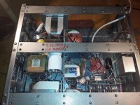
 old and new choke input Wave IO plus Belleson 5 volt 400mA .jpg111.6 KB · Views: 286
 -
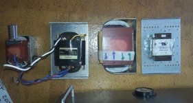
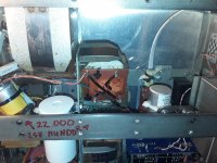
 Triad split bobbin, 6000mH 0,5 A , 22000mF, 250mH 0,85 ohm 10000mF.jpg148.4 KB · Views: 272
 -
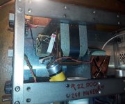
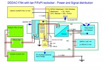
 Update voeding april2021.jpg156.7 KB · Views: 285
 -
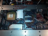
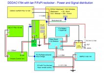
 Update voeding april2021A.jpg161.1 KB · Views: 271
 -
 update voeding april2021B.jpg138.5 KB · Views: 278
I spent many weeks conducting A-B testing to hear the differences between my WaveIO path with my very expensive Lumin streamer as a source and comparing it to my Pi3
Both paths were sent the same music in total sync using Roon. The outputs of both paths were switched by remote controlled relays and the music then went to Ian FiFoPi which went directly into the I2S of the DDDAC
There sound was totally the same and I listened for weeks with different music.
The streamer was sold and WaveIO removed
Fantastic testing and with a great result for me
Thanks for sharing your impressions Simon. They are 1:1 with my impressions, that the FiFoPi makes the input transparent (enough to me at least 😉 )
I connected the waveIO to the output of the PI (just for test purpose)
I keep the WaveIO as I do also testing with my DAC on other stuff, so it is good to have a USB input in my DAC
I connected the waveIO to the output of the PI (just for test purpose)
I keep the WaveIO as I do also testing with my DAC on other stuff, so it is good to have a USB input in my DAC
Hello Simon,
I guess you have figured it all? out?
Probably after the summer i will throw away both Aurender and wave IO and get myself a Roon subscription and a Roon nucleus to start streaming and also playing my ripped CD collection now present on a external HD.
Simon can you publish a drawing of your present set up. To ME it looks like Andrea in Italy will soon make some things available that could be interesting. Of course if you can diminish the impact of the power supply by using a tiny extra circuit somewhere that could be nice.
Like in the time when people did install Tent shunt themselves on the old boards some projects with lots of extra circuit boards and supplies end up looking like Vietnamese powerline distribution. IF you wanna use supercaps i think they should be close to the circuit it is feeding. A 500 Euro or more slick chassis separate supercap supply with lots of connectors, solder joints and half a meter DC cable is close to crazy. If these companies care so much about quality they should offer their customers a unit coming with a direct dc cable coming with a 2 euro strain relief. When ordering you just tell them the length needed. The chassis part and the cable part of the connection and the connection itself will be gone.
Doede told me he will reveal some more info on the advantages of supercaps on his blog. So probably it will get easier for us to start using them in the areas where they can be beneficial.
Greetings, eduard
Attachments

Hello Simon,
Thank you. So far i just pimped the power supply. Not that difficult to do and the effects are wonderful.
Greetings, eduard
P.s But it seems the getting rid of the Aurender is the next step to make.
Thank you. So far i just pimped the power supply. Not that difficult to do and the effects are wonderful.
Greetings, eduard
P.s But it seems the getting rid of the Aurender is the next step to make.
Adding a FiFoPi with good oscillators is cheaper, easier, and will improve the sound more than the PSU stuff, if you ask me.
Hello Simon,
Thank YOU.
This was the set up posted by Andrea Mori which includes some different point of views. One of the things he likes to focus on is separating the clock boards and make it possible to use optical and HDMI cables.
Greetings, Eduard
P.s would be nice to have some parts a bit separated ( near the modem for instance) because in my rack dont have that much space. I can install some circuits in my DDDAC chassis and under the DDDAC i can put the Roon Nucleus with a big 58F 16 volt supercap package.
Attachments
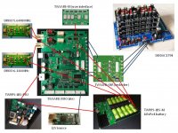
The Andrea Mori clocks seem to perform pretty well, but they are not exactly easy. Your setup involves eight boards just for the clock,plus a Roon Nucleus, and a supercap package for the Nucleus! Now I can see why you are worried about the complexities of moving away from the WaveIO + Aurender... why don't you just use a RaspberryPi with a FiFoPi board? That would be sooooo much simpler, but still super-duper good!
Hello,
There is not a lot of improvement possible in the rest of my set up unless i wanna invest the amount of a nice secondhand car. So getting a few extra boards in '' this area '' will be easier. It is more the problem of combining different boards from different sources.
Is it called handshake?
Greetings, Eduard
Hello Simon,
Thank YOU.
This was the set up posted by Andrea Mori which includes some different point of views. One of the things he likes to focus on is separating the clock boards and make it possible to use optical and HDMI cables.
Greetings, Eduard
P.s would be nice to have some parts a bit separated ( near the modem for instance) because in my rack dont have that much space. I can install some circuits in my DDDAC chassis and under the DDDAC i can put the Roon Nucleus with a big 58F 16 volt supercap package.
Yes I am aware of that clock set up which is exactly my next step Edward as I have purchased his clocks too 😁
So to confirm my system will use Andrea clock with the FiFoPi and I already use Ian Canada battery PSU with super caps as well
The PSU will power the FiFoPi and the clocks
The PSU will power the FiFoPi and the clocks
I recently went back from Cinemags to capacitors on my 4 deck version. I detected the sound was hard and not as fluid. Also, the right channel seemed a tad louder than the left and the image was shifting towards the right on almost all recordings.
I wanted to see if everything was connected alright inside the dac and checked the voltages. Here are a few things that I find not so correct.
- My PSU's 12V section is only outputting 10.6V in place of the designed 12V. Hence, the voltage coming in to the Dac's motherboard is also 10.6v in place 12V.
Q: What could be going wrong because of this lesser voltage? Could this impact the dac electrically and could it have an adverse effect on sound?
- The voltages in the single ended mode (capcitor coupled output) are as follows:
Right channel output (between POS and COMMON): 2.75 Volts
Left channel output (between POS and COMMON): 2.67 Volts
Q: Is this voltage imbalance big enough to translate into a perceivable listening experience where I hear the right channel dominantly over the left one?
Q: Could this imbalance be due to the 10.6V that my PSU is supplying to the dac's motherboard?
Q: I was not getting a perceivable left and right channel difference when listening via the Cinemag transformers.
Q: I am using .47uf capacitors to block the DC, is this value ok?
Q: I am using 470K bleeder resistors across the RCA plugs. Is this value ok or should the values change?
Deeply appreciate help from all the tech gurus out here including Doede. Thanks.
Check the voltages at the negative outputs of both channels (NEG to Common). If there is a bigger difference compared to POS-Common then you have DC offset and the transformer can come into saturation if difference is high enough. It is best to directly measure the offset on each channel, POS to NEG output. 10.6V power supply instead of 12V means that there may be a fault in the power supply module, and maybe some of the DAC boards are consuming too much power, so it is faulty. Disconnect power module from the DAC and see if it has 12VDC without load.
By the way, if it's no secret, which Cinemag transformer do you use?
By the way, if it's no secret, which Cinemag transformer do you use?
Last edited:
Secret!! Good one, I have perhaps mentioned that ten thousand times. Those are the CMLI 15/15B.
Would you mind having a stab at answering the other questions while others including Doede chip in.
Firstly wish to know what should be the value of the output capacitors that I should use. I believe .47uf for 4 boards should be small. Should it not be 2.2uf or something greater? Perhaps even 10uf?
Would you mind having a stab at answering the other questions while others including Doede chip in.
Firstly wish to know what should be the value of the output capacitors that I should use. I believe .47uf for 4 boards should be small. Should it not be 2.2uf or something greater? Perhaps even 10uf?
Caps has nothing to do with nr of boards, only with the load after that... like your preamp or volume control...
F low -3dB = 1 / (6,28 * C * Rload ) Hz
F low -3dB = 1 / (6,28 * C * Rload ) Hz
I recently went back from Cinemags to capacitors on my 4 deck version. I detected the sound was hard and not as fluid. Also, the right channel seemed a tad louder than the left and the image was shifting towards the right on almost all recordings.
I wanted to see if everything was connected alright inside the dac and checked the voltages. Here are a few things that I find not so correct.
- My PSU's 12V section is only outputting 10.6V in place of the designed 12V. Hence, the voltage coming in to the Dac's motherboard is also 10.6v in place 12V.
Q: What could be going wrong because of this lesser voltage? Could this impact the dac electrically and could it have an adverse effect on sound?
- The voltages in the single ended mode (capcitor coupled output) are as follows:
Right channel output (between POS and COMMON): 2.75 Volts
Left channel output (between POS and COMMON): 2.67 Volts
Q: Is this voltage imbalance big enough to translate into a perceivable listening experience where I hear the right channel dominantly over the left one?
Q: Could this imbalance be due to the 10.6V that my PSU is supplying to the dac's motherboard?
Q: I was not getting a perceivable left and right channel difference when listening via the Cinemag transformers.
Q: I am using .47uf capacitors to block the DC, is this value ok?
Q: I am using 470K bleeder resistors across the RCA plugs. Is this value ok or should the values change?
Deeply appreciate help from all the tech gurus out here including Doede. Thanks.
Q1 you need MINIMUM 12 Volt, everything else will spoil the bias. 12.5 measured at the PSU is best
Q2 yes might be
Q3 I cannot comment this, to many unknown variables for remote diagnostic
Q4 see my other response
Q5 value is fine
- Home
- Source & Line
- Digital Line Level
- A NOS 192/24 DAC with the PCM1794 (and WaveIO USB input)