Thanks, Extreme_Boky!
My transformer is 2x18V and as far as I remember my rails were at about + and - 21.6V when I measured under the load. The bias is at the recommended ~400mV accross the resistors and I would not want to increase it as the build is in 4U-30cm deep chassis and it runs hot enouhg to my liking. Also, I don't care so much about the power rating, 20W is more than enough for me.
I would mostly want to understand if my findings make sense because I am less than one-year-old DIYer with 6 amps") so climbing up the steep learning curve
so climbing up the steep learning curve
My transformer is 2x18V and as far as I remember my rails were at about + and - 21.6V when I measured under the load. The bias is at the recommended ~400mV accross the resistors and I would not want to increase it as the build is in 4U-30cm deep chassis and it runs hot enouhg to my liking. Also, I don't care so much about the power rating, 20W is more than enough for me.
I would mostly want to understand if my findings make sense because I am less than one-year-old DIYer with 6 amps
so climbing up the steep learning curve Thanks, Extreme_Boky!
My transformer is 2x18V and as far as I remember my rails were at about + and - 21.6V when I measured under the load. The bias is at the recommended ~400mV accross the resistors and I would not want to increase it as the build is in 4U-30cm deep chassis and it runs hot enouhg to my liking. Also, I don't care so much about the power rating, 20W is more than enough for me.
I would mostly want to understand if my findings make sense because I am less than one-year-old DIYer with 6 amps
4U/300 is a bit on the light side heatsink-wise for the Aleph J build, it being one of the hotter running designs from NP.
Just wanted to share an update and express some success, thanks to the patient minds here, and my all but frustrated self!
While I'll never know what the issue was with the bad board, to be honest, I went over it so many times I lost sight of what it might have been. I can tell you what it wasnt, which was my JFETs or MOSFETs.
The "good board" was operating normally, but not biasing - turning out to be a bad pot in position R27, which I mistakenly replaced with a 100K that didnt get me the desired results, only to realize that 200K is appropriate.
I did find that feeding the boards with a lab supply allowed me to more peacefully work the issues out, FWIW!
Followed most of Extreme_Bokys mods here, ommitted R13, 14 and Q3, as well as bridged C1. Currently no C6/7 since they are OOS of the right spec. I biased it to 490mv and getting a nice 0.0 of DC offset. Left it on overnight, just a quick test and it sounds great so far, about to put her in the new home proper.
Possibly considering adding a bi-polar cap to PSU board if thumps prove to be an issue, have ordered some along with another project's parts in case that's a needed change!
Built in a 3U case nice and tidy, need to clean up the wires to the PSU as you can see. I also found these super quiet 120MM fans that can be daisy chained and triggered by the power strip. They keep it all very cool and they are dead quiet. So, food for thought!
Lastly, I ended up ordering 20 Toshiba JEFTs with Punky on eBay, planning on building a matching jig and will likely offer them up at cost to other DIYers since I wont need that many for a while!
Comments, concerns, criticisms and all welcome!
490mV bias is a "Touch too Much"
for that case; however, whit those fans, it should be okay. I used the 5U case and have the same bias as you do.... and I can tell you -> that's hot!I see that you like the sound, which is the ultimate goal.
I also like how you doubled up on the power rail wires - great decision. You should do the same with the speakers' wire links.
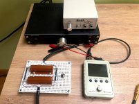
Zen Mod, I used Akitika signal generator and Noir pre-amp for the sine (as Akitika alone gives about 1.5V max, not enough). I used 8ohm 100W power resistor as load. Picture of my gear attached. The load gadget also has another 8ohm switchable resistor for 4ohm load.
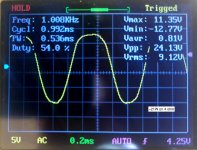
By the way, when I tried 4ohm load, I did not see clipping even on ~9Vrms (~21W) while "officially" Aleph J is only 13W on 4ohm. Picture also attached.
By the way, when I tried 4ohm load, I did not see clipping even on ~9Vrms (~21W) while "officially" Aleph J is only 13W on 4ohm. Picture also attached.
Attachments
Measured as you said, Zen Mod.
Output being at ~5VAC, I have:
53mV AC across R17 and
90mV AC across R19.
Both channels the same.
Funny thing is that I do not see it clipping so badly as yesterday (I did some adjustments though both in bias and in offset). Now my left channel seems to start clipping at about 13.5V on 8ohm (~23W) and the right channel is perfectly fine: clips just above 14.1V as expected. Also, both channels clip on 4 ohm at about 8V (16W). So, either the adjustments helped, or my "toy" oscilograph is not the thing I should use.
But I noticed another strange thing. When inputs are shorted or connected to something (signal generator this time), the DC offset is fine on both channels (around +-5mV). But if I leave the inputs open, then the right channel is still fine, but the left channel DC offset increases and starts floating between 75-100mV. What's that??
And one more question. When setting bias current, across what resistors should I measure, as voltage on all of these are a bit different (in mV). Or the differencec that small does not matter?
R17 R16 R19 R18
372 414 395 396
416 390 385 423
All Mosfets run at about 55C measured at their bolts.
-Alvis
voltages at source resistors should comply with their tolerance ( 5%) and with tightness of mosfet matching
so, calc is easy
if you have that condition, it's irrelevant on which source resistor you're going to observe for Iq
you're in 10% bracket, so all OK
next time, build Aleph with just one pair of IRFP150, so no matching worries

so, calc is easy
if you have that condition, it's irrelevant on which source resistor you're going to observe for Iq
you're in 10% bracket, so all OK
next time, build Aleph with just one pair of IRFP150, so no matching worries
490mV bias is a "Touch too Much"
I see that you like the sound, which is the ultimate goal.
I also like how you doubled up on the power rail wires - great decision. You should do the same with the speakers' wire links.
Thanks for the compliments! Yes I wanted to get a little extra gauge in there and figured the twisted pairs would offer some secondary benefits!
On the note of sound, ive been combing through to fine more information on “tuning” but I’ve been impressed by the bass response. More than any other amplifier has offered with these speakers - I “feel” the bass plucks and bass drum.... BUT I did find it a bit boomy and imprecise at times. Not sure if this is a burn-in issue or if it can be related to bias at all? Those fans work wonders without them I think I’d be at 400mV
Checked on this speaker terminals and they are feeling good! Good looks
Yes, the bass control and extension is insane.... once the C1 is shorted, and the short circuit protection is removed.
You will notice another jump in bass control if you double-up that speakers' wire, as I mentioned in my previous post... or even better, ditch the multicore wire and use a solid core copper wire for DC and speaker wiring - this will remove the boominess (you could also try a different power cord!)
Happy listening!
Edit:
Check this post:
https://www.diyaudio.com/forums/pass-labs/363046-aleph-c1-4.html#post6562113
...or even better, read the whole thread.
Last edited:
Well, I have to say I am still not happy with my Aleph J. I have built ACA, M2X and F5 before and all went perfectly well, but one of my Aleph channels happens to be a bit whimsical.
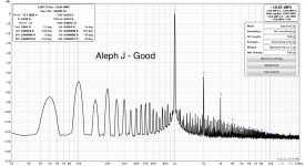
I made distortion measuments and I do not like what I see.
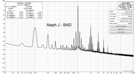
The first image is of my bad Aleph channel. You can see a lot of intermodulation between 1kHz and 100Hz buzz, the buzz itself is very high, and THD is whopping 0.46%.
The second image is of the good channel. I do not like all this comb, but THD is acceptable at 0.063%.
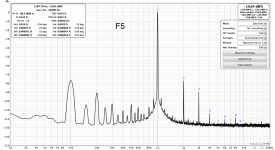
Just for comparison, I include the image for my F5 measured with the same tools (REW and Focusrite 2i2, 2V83 on 8ohm) on the same time. This looks much better.
My journey with Aleph started with a hickup as I did not used good thermal interconnect on mosfets, so for a few hours my mosfets (and especially this bad channel) ran at quite high temperatures (I did measured close to 150C at some short time once, and this is at the case). Overall looks like mosfets survived and now, after changing to aluminum oxide thermal pads, they all run at about 50C at case, and voltages on R16-R19 are ok (434, 390, 415, 415 mV respectively), DC offset is also fine (+- a few mV when the amp is warmed up).
What could be the reasons of this high THD and intermodulation on this bad channel?
Where should I start my investigations. Being a noob, I hope for some guidance.
I made distortion measuments and I do not like what I see.
The first image is of my bad Aleph channel. You can see a lot of intermodulation between 1kHz and 100Hz buzz, the buzz itself is very high, and THD is whopping 0.46%.
The second image is of the good channel. I do not like all this comb, but THD is acceptable at 0.063%.
Just for comparison, I include the image for my F5 measured with the same tools (REW and Focusrite 2i2, 2V83 on 8ohm) on the same time. This looks much better.
My journey with Aleph started with a hickup as I did not used good thermal interconnect on mosfets, so for a few hours my mosfets (and especially this bad channel) ran at quite high temperatures (I did measured close to 150C at some short time once, and this is at the case). Overall looks like mosfets survived and now, after changing to aluminum oxide thermal pads, they all run at about 50C at case, and voltages on R16-R19 are ok (434, 390, 415, 415 mV respectively), DC offset is also fine (+- a few mV when the amp is warmed up).
What could be the reasons of this high THD and intermodulation on this bad channel?
Where should I start my investigations. Being a noob, I hope for some guidance.
Attachments
well, you can expect some damage to these scorched mosfets
only one way to inspect are they the culprit ...... to put other ones in
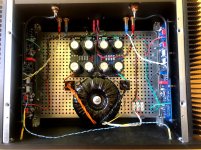
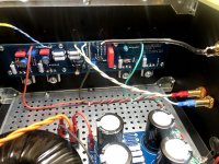
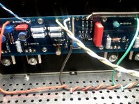
though, it would be useful to see pics of your actual build, then think a little about your wiring and PSU generally - I don't like that high weed left from 1KHz
only one way to inspect are they the culprit ...... to put other ones in
though, it would be useful to see pics of your actual build, then think a little about your wiring and PSU generally - I don't like that high weed left from 1KHz
Yes, changing the mosfets is the last thing I would like to do as I would also have to order them matched from diyAudio perhaps. But I will go with that eventually if nothing else helps.
Meanwhile, here are a few photos of my build. Power supply is on the universal PSU PCB from diyAudio store, caps are Nichicon 18000uF 35V 85C. Input wiring is done with 2 wire shielded cable, the shield is connected to IN- only on one end (on the RCA), IN- and GND on the PCB is shorted.
Thanks, ZM, for looking into that!
Attachments
- Home
- Amplifiers
- Pass Labs
- Aleph J illustrated build guide