*Please forgive me for posting this in the Tubes/Valves forum, but seemed a more appropriate place than Digital Line Level considering the subject matter.
I've hit a snag with my current project and am hoping someone here might point me in the right direction. The project is a major reworking of my ANK DAC 2.1, consisting of a new power supply section for the DAC board and redesigned circuit boards for the power & analog output sections. The only parts left from the original kit are the DAC board itself and the main transformer & choke.

Sadly I am neither an engineer nor DIYer with years of experience; just a hobbyist who likes to bite off more than he can chew.
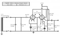
All of the new power supply boards are working as intended, however I have struck an issue upon connecting the B+ and filament PS boards to the tube output board. The output board is very similar to the version in the original DAC, but has been altered to accommodate the 5670 tube type instead of the 6DJ8 (I had been using the Russian 6N3P with an adapter previously). The other significant change was the addition of a heater elevation circuit, and it is this which is not operating as expected.
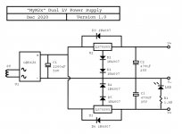
The new ANK M2x power supply has been split into two redesigned boards, one for B+ and one for the 5670/6N3P filaments. When connected to the output board the B+ supply works fine but the 6N3P heater supply fails to produce 6.3 volts. The filament negative (zero volt) is elevated to 62V as predicted, but the positive also reads 62V, rather than 68.3V as I would have thought. It's quite obvious just looking at the tubes that the heaters are not functioning.
When I disconnected the elevation circuit the heaters and their power supply started to function normally. The heater supply is not independent - it utilises a single winding on the same transformer that the B+ supply is connected to, along with a single rectifier and filter cap that feeds two 7805 regulators. So I'm wondering if I've made a mess of the elevation circuit on the PCB itself, or if there's an issue with the power supply configuration that means it's unable to be used in this way?
Or something else of course...
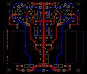
Attached are my modified ANK schematics and the PCB design for the 5670 analog output board.
I've hit a snag with my current project and am hoping someone here might point me in the right direction. The project is a major reworking of my ANK DAC 2.1, consisting of a new power supply section for the DAC board and redesigned circuit boards for the power & analog output sections. The only parts left from the original kit are the DAC board itself and the main transformer & choke.
Sadly I am neither an engineer nor DIYer with years of experience; just a hobbyist who likes to bite off more than he can chew.
All of the new power supply boards are working as intended, however I have struck an issue upon connecting the B+ and filament PS boards to the tube output board. The output board is very similar to the version in the original DAC, but has been altered to accommodate the 5670 tube type instead of the 6DJ8 (I had been using the Russian 6N3P with an adapter previously). The other significant change was the addition of a heater elevation circuit, and it is this which is not operating as expected.
The new ANK M2x power supply has been split into two redesigned boards, one for B+ and one for the 5670/6N3P filaments. When connected to the output board the B+ supply works fine but the 6N3P heater supply fails to produce 6.3 volts. The filament negative (zero volt) is elevated to 62V as predicted, but the positive also reads 62V, rather than 68.3V as I would have thought. It's quite obvious just looking at the tubes that the heaters are not functioning.
When I disconnected the elevation circuit the heaters and their power supply started to function normally. The heater supply is not independent - it utilises a single winding on the same transformer that the B+ supply is connected to, along with a single rectifier and filter cap that feeds two 7805 regulators. So I'm wondering if I've made a mess of the elevation circuit on the PCB itself, or if there's an issue with the power supply configuration that means it's unable to be used in this way?
Or something else of course...
Attached are my modified ANK schematics and the PCB design for the 5670 analog output board.
Attachments
Did you connect the V- of the filament supply to ground by mistake? The entire filament supply must be floating at 62 volts and not connected to other devices.
The heater elevation circuit you have is for AC heater voltage not the DC heater circuit you have.
Did you connect the V- of the filament supply to ground by mistake? The entire filament supply must be floating at 62 volts and not connected to other devices.
Not that I'm aware of. The reason I did new designs splitting the B+ & filament PCBs was to avoid that issue. The original M2x PS board has filament V- connected to main GND.
Thanks for your response.
The heater elevation circuit you have is for AC heater voltage not the DC heater circuit you have.
Would you be willing to elaborate? I thought they were fundamentally the same.
I certainly am capable of being that dense though.
The heater elevation circuit you have is for AC heater voltage not the DC heater circuit you have.
What Alllensoncanon is saying is that if you were using a center tapped AC htr supply from a transformer,it would be floating, by floating we mean it is not referenced to the rest of the amp circuit. Usually the CT of an AC htr supply would be connected to ground,therefore it is referenced to your amp circuit.Would you be willing to elaborate?
Your using a DC supply, which is harder to elevate; where are you connecting the 62v by the way? If you connect +62v on the rail marked "-" then the diodes in that bridge rectifier will pass that +62v to both the LS78S05's,you'll then get 60v ish on both sides of your heater. Draw the BR properly with individual diodes, you'll slap your head and utter the immortal word - "Doh!"
Andy.
Thanks Andy, I appreciate your response, and you're right the "-" output from the power supply is connected between the resistors forming the voltage divider on the output board (at 62V). My (false) impression was that what you're describing would happen, but the positive rail would still be 6.3V higher than the negative.
I think perhaps during my research I have confused DC referenced AC heater elevation with DC heater elevation.
The inspiration for this was a similar circuit used in the John Broskie designed Aikido board I built my preamp with. It seems to work fine with DC heaters, and at least to my eyes is put together in much the same way with R13 & R14 forming the divider.


I don't see any obvious mistakes here.
Is it possible that 7805 heatsinks are touching something they shouldn't? Chassis, for example (via the screws or whatever is used to fox them to the PCB)?
Is it possible that 7805 heatsinks are touching something they shouldn't? Chassis, for example (via the screws or whatever is used to fox them to the PCB)?
You could always try elevating your heater circuit at the 8v AC winding, use a couple of 220r resistors in series across the winding, apply your 62v to the center of the two 220r resistors.
Andy.
Andy.
I don't see any obvious mistakes here.
Is it possible that 7805 heatsinks are touching something they shouldn't? Chassis, for example (via the screws or whatever is used to fox them to the PCB)?
It'd be very unlikely, but I'll have a look. The heatsinks have been isolated from the regulators, so in theory even if that were the case there would be no harmful effect, right?
Tough one this one. AC or DC does not matter. It should work OK:
- as long as the PSU for the heater is really floating.
- the winding for the heaters DC is not used for anything else
- the winding is really floating so no connection other than the rectifier and DC circuit
- and it is solely used for the heaters and no heater is connected to GND.
It seems you have a short somewhere. Dumb question: what happens if you disconnect either one of the 7805?
BTW not to make matters more complex but you could have chosen just 1 LDO reg with higher current capacity and slow start. Just saying.
Last edited:
Try shorting C7/C8. Does it work now?
I am going to remove those caps completely and see if it makes a difference. Strictly speaking, I think they're unnecessary anyway.
You could always try elevating your heater circuit at the 8v AC winding, use a couple of 220r resistors in series across the winding, apply your 62v to the center of the two 220r resistors.
I might try that Andy. That is essentially how the heater elevation works for the 6x5 and 6bm8 on the B+ board (although their heaters are AC powered).
The heater elevation is not included on the original output board. I considered it would be a nice addition, since the heater-cathode ratio for the first triode in each tube is about 130V. A bit high for the 6DJ8 or 5670 I would have thought.
Tough one this one. AC or DC does not matter. It should work OK:
- as long as the PSU for the heater is really floating.
I think it is. It is only connected to the heater pins at the output end and the transformer at the other.

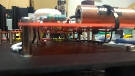
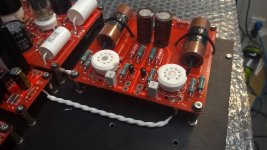
Here is the tranny end. On the the left hand side there are the 300-0-300 & 6.3 volt windings going off to the right to join the B+ board. The green wire connects the B+ board GND to the chassis.
The heater PSU is connected to the 8 & 0 of the 8-0-8 winding on the right. I assume both power supplies sharing the transformer in this way is okay?
The transformer also has a ground wire connected to the chassis.
I think this is all true, but I will have to recheck everything.- the winding for the heaters DC is not used for anything else
- the winding is really floating so no connection other than the rectifier and DC circuit
- and it is solely used for the heaters and no heater is connected to GND.
I was wondering that exact thing myself.It seems you have a short somewhere. Dumb question: what happens if you disconnect either one of the 7805?
You're not wrong, and I did consider it. In the end because I was using the original transformer I decided not to mess with that part and keep it as designed.BTW not to make matters more complex but you could have chosen just 1 LDO reg with higher current capacity and slow start. Just saying.
What could go wrong? 🙄
A couple more photos attached:
Attachments
That is correct. In theory 😀It'd be very unlikely, but I'll have a look. The heatsinks have been isolated from the regulators, so in theory even if that were the case there would be no harmful effect, right?
BTW, you don't need two separate voltage elevators in this configuration - you're shorting them with the common heater V- anyway. Shouldn't be the cause of the problem though.
The transformer also has a ground wire connected to the chassis.
You mean PE ? Please use correct terms! PE is for safety, Audio GND is ground at the secondary side of the transformer and used for the audio circuits as well. Which wire and is it connected to a secondary winding as well ? Or is it the shield connected to PE ? Some possibilities .....
Please also try out disconnecting either one of the 7805. BTW with 8V available you could have used LM317 for soft starting the heaters, it is just a cap extra. Small investment, possibly larger return value.
Point is not the nice way of building but the lack of a schematic where all things are drawn in. I think we could then see where it goes wrong.
Last edited:
Your comment made me curious TG.That is correct. In theory 😀
BTW, you don't need two separate voltage elevators in this configuration - you're shorting them with the common heater V- anyway. Shouldn't be the cause of the problem though.
Yesterday after the heaters failed to work I disconnected the elevation part of the circuit by lifting the resistor leads for R11 & R13. The heaters and the power supply functioned properly, although obviously not elevated.

After reading your comment I decided today to reconnect the elevation but only on one side of the board to see what would happen. The heaters started to work correctly with 6.3V across + & -, but the elevation was only 35V. I then reconnected the resistor on the other side and now everything appears to be working perfectly. I have both tube heaters functioning normally at 6.3V with an elevation of 62V on the negative rail!
You might expect I'd be happy about this, but I'm too busy being dumbfounded. Everything is now configured in the same way as it was yesterday when it wasn't working.
My apologies, yes I should have been more clear. The audio ground (connected to GND on the B+ board) and the transformer shield are both connect to protective earth.You mean PE ? Please use correct terms! PE is for safety, Audio GND is ground at the secondary side of the transformer and used for the audio circuits as well. Which wire and is it connected to a secondary winding as well ? Or is it the shield connected to PE ? Some possibilities .....

- Home
- Amplifiers
- Tubes / Valves
- Why is this heater elevation circuit not working?