Your heaters use 350mA, when switching on, the current is about 3 times higher until the filament is hot. Your regulator limits at 1A, that is too close.
Get a LM317 instead.
Get a LM317 instead.
You could be right. That's the kind of thing I was looking at how to test for. Thank you.Valve heaters are a considerably heavier load when cold than when warm. That's how they self-regulate, like an incandescent light bulb. Could what you're seeing be the regulator going into current overload protection and staying there?
YOS,
Chris
In fact, it sounds like bansuri concurs...
Thanks bansuri. Yes, I had been thinking of following jean-paul's advice from earlier in the thread regarding the LM317. I will breadboard a similar power supply with that regulator and see what happens.Your heaters use 350mA, when switching on, the current is about 3 times higher until the filament is hot. Your regulator limits at 1A, that is too close.
Get a LM317 instead.
Your explanation makes sense. It makes me wonder though, how has my DAC 2.1 not had this issue before? The 6DJ8 has a similar current draw also.
I've had similar issues with a LM317 based DC htr supply, I presumed from the 317 going into protection. I solved my issue by using the LM317 regulator board with an outboard TIP3055. The fault occured even though the valves current requirement was under the DC supplies Imax. At SW on current draw is over 3.5A, which AFAIK is a tricky load for any regulator IC.
You could try a big thermistor or failing that pop a big 1k resistor on a one leg of the tfmr 8v winding, after SWing on short out the resistor with a jump lead; if this works then it indicates a possible issue with one of your reg IC's or an iffy joint somewhere on your board.
Another possible fault might be one of your valves having a heater cathode short, or intermittant Htr/K SC.
Andy.
I've had similar issues with a LM317 based DC htr supply, I presumed from the 317 going into protection. I solved my issue by using the LM317 regulator board with an outboard TIP3055. The fault occured even though the valves current requirement was under the DC supplies Imax. At SW on current draw is over 3.5A, which AFAIK is a tricky load for any regulator IC.
The notion of switch-on current causing these issues with regulators and heaters is interesting, if disconcerting. It has reminded me though that I have a few LD1804's lying around, which is the same reg that the filament power supplies in my Aikido preamp use.
In that preamp I'm currently running 6N6P & 6N23P tubes, making the heater current 1.06A per side. The initial current draw must be significant, but the LD1084 seems to handle it.
Chris Hornbeck;Could what you're seeing be the regulator going into current overload protection and staying there? said:Fully agree. Easily checked by measuring regulator input voltages when connected. Alternatives could be a power transistor in parallel to the regulator to improve the output current or altogether replace regulators with a high wattage series resistor. Regards.
This is a known problem for the OP's regulator where you have the ref pin 'jacked up' using a couple of diodes. On a cold start the output is pulled basically to zero by the cold heaters, but the ref pin is elevated by whatever ref current flows in the diodes, or something like that. With the output pulled below the ref pin, the regulator goes into sulk mode. One fix might be to put a resistor in parallel with the regulator to allow some start-up current to bypass the reg. Or swap to a more conventional 317 circuit.The notion of switch-on current causing these issues with regulators and heaters is interesting, if disconcerting.
Last edited:
Thanks everyone. I really appreciate your patience and your insight here.
I have all the parts to put together a LD1084 based power supply as a test, but if there's something particular about the LM317 that makes it a better option I can easily buy some.
Quickly skimming the datasheets for each regulator it looks like one could design a PCB that accommodates either kind - provided one of the regs and its heatsink can be twisted 180 degrees due to the reverse pinout. (edit: a quick google search confirms this is already a thing)...
I built SY's schematic for 'his masters noise' phono stage, it uses LM337 and LM317, one tube heater is -ve, the other +ve 6.3V for additional noise cancellation. Be sure to use 'not a low ESR cap' on the output as it is (apparently) inductive - you can read more about this via google and 'tnt audio', they did quite some investigations into LM317, to the point where 'all the test work has been done'.
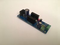
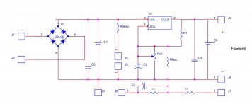
This is the pcb done by me that normally use without any type of problem, it contain also the little circuit for elevation with jumper to use , in case
The LM350 works fine; it is present also a trimmer to regulate the voltage
Walter
The LM350 works fine; it is present also a trimmer to regulate the voltage
Walter
Attachments
I built SY's schematic for 'his masters noise' phono stage, it uses LM337 and LM317, one tube heater is -ve, the other +ve 6.3V for additional noise cancellation. Be sure to use 'not a low ESR cap' on the output as it is (apparently) inductive - you can read more about this via google and 'tnt audio', they did quite some investigations into LM317, to the point where 'all the test work has been done'.
Both very interesting, thanks! Some regulator datasheets I've read through (like the LD1084 & LT1963) do specify the need for some degree of ESR for the output to function correctly, but that TNT audio series shows very well exactly what that means in practice.
This is the pcb done by me that normally use without any type of problem, it contain also the little circuit for elevation with jumper to use , in case
The LM350 works fine; it is present also a trimmer to regulate the voltage
Walter
Nice! Putting the elevation circuit on the power supply board is something I hadn't even considered...
This morning I put together a LD1084 based power supply on a perfboard. Same configuration - single rectifier & smoothing cap feeding two regulators. Tested by powering up for 1 minute every half-hour and it performed without fault, so cross-fingers this battle has been won.
Thanks again for your help everyone.
It still makes me wonder why, with the original circuit, I'd never experienced this issue with the official ANK kit. Not in the 3 years since building it. I've not read of others suffering in such a way either. A flaw in my new board design perhaps?
Thanks again for your help everyone.
It still makes me wonder why, with the original circuit, I'd never experienced this issue with the official ANK kit. Not in the 3 years since building it. I've not read of others suffering in such a way either. A flaw in my new board design perhaps?
“The fault, dear Brutus, is not in our stars / But in ourselves, that we are underlings.” (Julius Caesar, Act I, Scene III, L. 140-141)
Sorry, couldn't resist the temptation,
Chris
Sorry, couldn't resist the temptation,
Chris
- Home
- Amplifiers
- Tubes / Valves
- Why is this heater elevation circuit not working?