the underlying principle with tube circuits is that no element inside the tube envelope must be left hanging and not connected to anything, be it filaments or even internal shields. you either connect one side to ground of use ground lifting circuit...dc coupling between stages takes more attention and some complication.....merlinb has a blog....The Valve Wizard
Not that I'm aware of. The reason I did new designs splitting the B+ & filament PCBs was to avoid that issue. The original M2x PS board has filament V- connected to main GND.
Thanks for your response.
I didn't look close at what you were doing but the way I did an Allen Wright design I made up myself and using a Curcio power supply board and all I did was put a pair of 100k resistors tied together at one end and then I put the open ends right between pins 4 and 5 of the 6922s. I then then sourced 100vdc to connect at the ends of the 100k that were tied together and it worked great.
I also had DC fil.Now, you can use 220k resistors if you want.
Valve Wizard is a great resource. A lot of what I've learned about tubes has come from that site.the underlying principle with tube circuits is that no element inside the tube envelope must be left hanging and not connected to anything, be it filaments or even internal shields. you either connect one side to ground of use ground lifting circuit...dc coupling between stages takes more attention and some complication.....merlinb has a blog....The Valve Wizard
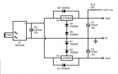
Following your line of thinking, is it too presumptuous to then say my original design is sound? The heater power supply on the original M2x board has the negative rail (0V) connected to audio ground (attached picture 1). That is good.
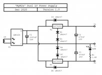
I then split the heater supply from the B+ supply (picture 2), disconnecting the negative rail from audio ground (making it floating?). That is bad.
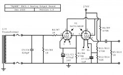
But then I connected the negative rail to the elevation circuit on the output board (picture 3), referencing it to a division of B+ (62V). That is good.
Is that in any way accurate?
Attachments
Today, when I have had opportunity, I have powered up and each time the circuit has worked as originally conceived. 6.3V across both heaters, elevated by 62V.
I'm having trouble duplicating the problem I had yesterday. Good, but not reassuring.
I'm having trouble duplicating the problem I had yesterday. Good, but not reassuring.
In your original setup you had one floating heater supply, but it was elevated twice, for each channel. There is a common 0Vdc for each heater supply and separate +6.2Vdc outputs. Could it be that you have switched which side of the heater supply that is being elevated, so it is the common 0vdc that is being raised? That would explain why you saw half the elevation when one half was raised.
The small invisible dab of solder somewhere on the PCB can drive you nuts sometimes. Happened to me more than once 🙂Y
You might expect I'd be happy about this, but I'm too busy being dumbfounded. Everything is now configured in the same way as it was yesterday when it wasn't working.
Glad that it works now!
Since only the upper resistors in the dividers were raised, 35V is totally reasonable.That would explain why you saw half the elevation when one half was raised.
With one divider the elevation voltage is 270V*82k/(270k+82k)=62.9V
With both dividers in parallel (output shorted by the heater V-) the voltage is 270V*(82k||82k)/(270k||270k+82k||82k)=270V*41k/(135k+41k)=
62.9V again
With lower resistors in parallel but with only one of the upper resistors the voltage is 270V*41k/(270k+41k)=35.6V
You are right, it is the common zero volt rail (V-) that is being elevated, however that has remained unaltered thoughout. It is a level of daftness baked into the design.In your original setup you had one floating heater supply, but it was elevated twice, for each channel. There is a common 0Vdc for each heater supply and separate +6.2Vdc outputs. Could it be that you have switched which side of the heater supply that is being elevated, so it is the common 0vdc that is being raised? That would explain why you saw half the elevation when one half was raised.
This means I am providing it two voltage references unnecessarily aren't I? That's what TG was trying to tell me in post #17, but I got distracted when the heaters started working.
I have been able duplicate this problem and cause the heaters to stop working again by swapping the 6N3P tubes around between the two channels, but I am still having trouble finding a pattern.
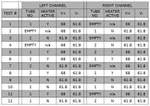
I've done twelve tests so far and here are the results. Each time, I let the power supply drain down to a few millivolts before swapping the tubes. Hopefully this chart is straightforward enough to read.

As you can see certain combinations worked sometimes but not others, which is particularly maddening. When the heaters are visibly active the voltages are as one would expect - 68V positive and 61.8V negative - indicating the elevation is working and there's approx 6.3V across the supply. When not visibly active both voltages are 61.8.
Interestingly, when a tube socket is left empty then its voltages are 68 & 61.8 whether the opposing channels tube heater functions or not. With both sockets populated the tube heaters either both function or both don't - one never operates while the other doesn't. Note: even when the heaters are non-functioning the transformer secondary is outputting 8VAC and the rectifier 10ish volts DC as expected.
One other thing I haven't made clear previously is that the polarity of the heater pins is different for each channel, with pin 1 being positive for the left channel but negative for the right. I had thought that it did not matter which way around they were. Was I wrong?
I've done twelve tests so far and here are the results. Each time, I let the power supply drain down to a few millivolts before swapping the tubes. Hopefully this chart is straightforward enough to read.
As you can see certain combinations worked sometimes but not others, which is particularly maddening. When the heaters are visibly active the voltages are as one would expect - 68V positive and 61.8V negative - indicating the elevation is working and there's approx 6.3V across the supply. When not visibly active both voltages are 61.8.
Interestingly, when a tube socket is left empty then its voltages are 68 & 61.8 whether the opposing channels tube heater functions or not. With both sockets populated the tube heaters either both function or both don't - one never operates while the other doesn't. Note: even when the heaters are non-functioning the transformer secondary is outputting 8VAC and the rectifier 10ish volts DC as expected.
One other thing I haven't made clear previously is that the polarity of the heater pins is different for each channel, with pin 1 being positive for the left channel but negative for the right. I had thought that it did not matter which way around they were. Was I wrong?
Attachments
So, I could remove the voltage divider & cap from one channel and the elevation would still be the same right?Since only the upper resistors in the dividers were raised, 35V is totally reasonable.
With one divider the elevation voltage is 270V*82k/(270k+82k)=62.9V
With both dividers in parallel (output shorted by the heater V-) the voltage is 270V*(82k||82k)/(270k||270k+82k||82k)=270V*41k/(135k+41k)=
62.9V again
With lower resistors in parallel but with only one of the upper resistors the voltage is 270V*41k/(270k+41k)=35.6V
Would there be any detriment in swapping the heater inputs to elevate the positive rail instead? Could the elevation of the common negative rail be causing my issue perhaps?
Correct.So, I could remove the voltage divider & cap from one channel and the elevation would still be the same right?
It depends. Should be fine with one divider, but I wouldn't do it with two dividers.Would there be any detriment in swapping the heater inputs to elevate the positive rail instead?
I don't think so.Could the elevation of the common negative rail be causing my issue perhaps?
Today I have attempted to troubleshoot my heater issue - with some success perhaps. This is what I have tried so far:
1. Removed capacitors C7 & C8 from the output board. No change.
2. Removed right channel voltage divider resistors R11 & R12 from the output board, so there was only one divider in the circuit. No change.
3. Lifted one leg each of the voltage divider resistors for the left channel, so disconnecting that divider from the circuit. Heaters were then non-elevated. No change.
That's right. Even with the elevation circuit removed I still had trouble with the heaters not activating. I had assumed the elevation circuit was the culprit because that's the part of the schematic I had altered, thinking I'd done a poor job of it.
It would make sense then that either the elevation wasn't the problem, or somehow the elevation circuit has damaged the heater power supply?
4. Throwing the dice, I then swapped the heater rails for the right channel, making pin 1 the positive rail (like it is for the left channel). Some change. This seems to have alleviated but not cured the problem.
Testing since, the result has been that the left channel heater activates 100% of the time, and the right channel about 70%. Also, for the first time one tube can function properly (always left channel so far), while the opposing one does not.
Next, I don't know. Maybe swap the left & right channel power supply outputs around? Replace the heater supply completely with another I've built?
Anyone have any clues on what's happening here?
Any success noted in the above post was short lived. The moment after I wrote it, both heaters failed to activate on next startup. So, it seems very much the same kind of results one might have flipping a coin 10 times and always getting Heads.
I then replaced the entire heater PS board with a duplicate I had made up. The heater problem persisted. That would eliminate a problem with the construction of the first board at any rate.
As one might expect, the regulator output measures zero volts whenever the corresponding heater doesn't work. I'll have to start investigating why the 7085s are randomly being affected like this. The rectifier is supplying 10V, I can't see any reason for thermal shutdown, and the current draw is well below 1A, so it's a bit of a mystery.
I assume there's something in the startup conditions freezing output at zero. There has been occasions where a non-functioning heater has come to life after quickly turning the power off and after about 5 seconds, on again.
You don't seem to measure anything, but write not working. Have you measured the output from the filament board? Regards.
You don't seem to measure anything, but write not working. Have you measured the output from the filament board? Regards.
I sure have.
Everything measures fine. 8 volts AC from the transformer, 10 VDC from the rectifier. These readings don't change whether the tube heaters function or not.
The power supply regulators both produce 6.3V as they should unloaded.
When the tubes are inserted into the output board and the B+ & heater supplies are powered on, one of three things can happen.
a) Both tube heaters illuminate. They both read 6.3V across the + and - rails.
b) One tube heater will illuminate, and one won't. The working heater will read 6.3V and the non-working heater 0V
c) Neither tube illuminates. Both heaters read 0V across the + and - rails.
B+ is always stable. But the heaters can fail to start, seemingly at random.
Post #29 contains some more measurements, but those are from when the heater elevation circuit was in play.
Is that what you meant?
When you are supplying DC to the filaments, why do you need elevation circuit?
Have you checked any other circuit connected to the filament supply board other than the elevated supply?
What is the voltage between the cathode and the elevation circuit? (for each cathode)
Regards.
Have you checked any other circuit connected to the filament supply board other than the elevated supply?
What is the voltage between the cathode and the elevation circuit? (for each cathode)
Regards.
Cathode for the first triode is at 130V. Over the max heater-cathode for the 5670 & 6922. Seemed easy enough to implement.When you are supplying DC to the filaments, why do you need elevation circuit?
Not yet, although it is not running elevated any more. Testing it with a different load is the next thing I will try.Have you checked any other circuit connected to the filament supply board other than the elevated supply?
First cathode at 130V, second cathode at about 2V, elevation of 60V. Although this problem occurs without the elevation circuit too.What is the voltage between the cathode and the elevation circuit? (for each cathode)
Regards.
Last edited:
Certainly there is a problem at the regulators with them delivering no voltage when it happens. I have to assume for the moment that the cause is external to the regulator though, or else I have four faulty regulators. That would be quite odd, wouldn't it?Intermittent regulator fault would be my guess.

- Home
- Amplifiers
- Tubes / Valves
- Why is this heater elevation circuit not working?