I built steps 1 and 2 on my PhiDeca and got the following test results using a 15V switching power supply and TP0 as the reference:
Power supply: 15.01V-15.02V
Step 1:
~~~~~~
TP1: 7.39V
TP2: 6.28V
TP3: 5.00V
TP4: 2.49V
TP9: 8.63V
Step 2:
~~~~~~
TP5: 6.23V
TP6: 1.87V <-- This is most concerning
TP7: 1.90V
TP8: 4.17V
Richard, I tested the LM317 and got the following results, per your message:
Pin 1: 7.39V
Pin 2: 8.64V
Pin 3: 15.01V (this pin is nearest to L1)
Please let me know what the next troubleshooting steps are. Thanks for your support!
Thinking out loud here - LM317 voltages indicate its likely working correctly as pin1 (ref) is 1.25V below pin2 (output). But pin1 voltage should be above 10V, created by the two zener diodes (D1,D2). Instead it seems to be the same voltage as TP1 which indicates D1 (4.3V) isn't passing any current to speak of (it should have 5mA running through it). And D2 voltage is way too high for a 6.8V zener (although we don't have a direct measurement of the voltage across it).
So to help me debug this further, please measure the voltage across D1 (4.3V). D2 (6.8V) and also across R10 (15R) and R9 (15R).
Let's not worry about getting step 2 voltages correct until we have step 1's voltages in the right ballpark.
So to help me debug this further, please measure the voltage across D1 (4.3V). D2 (6.8V) and also across R10 (15R) and R9 (15R).
Let's not worry about getting step 2 voltages correct until we have step 1's voltages in the right ballpark.
So to help me debug this further, please measure the voltage across D1 (4.3V). D2 (6.8V) and also across R10 (15R) and R9 (15R).
Sorry, do you mean to measure from cathode to ground? Using TP0 is the following:
D1: 7.38V
D2: 3.09V
R9: 7.39V
R10: 3.01V
No, by 'across' I meant put one probe on one side of the component and the other probe on the other side. When measuring across the resistors you may need a more sensitive range to be able to see something.
with the output cap 4.7uf how low is F3 frequency ---goes it down to 10hz or ??
have this output cap anything to do with the input impedance on my 4p1l pre amp ?
have this output cap anything to do with the input impedance on my 4p1l pre amp ?
No, by 'across' I meant put one probe on one side of the component and the other probe on the other side. When measuring across the resistors you may need a more sensitive range to be able to see something.
Across R9: 0.1mV
Across R10: 79.3mV
The zener diodes are common cathode, yes? So the 2 pins on the same side are the anodes, the 3rd pin is the cathode? Measuring from each of the anodes to the cathode:
D1: 4.29V / 76.7mV
D2: 4.94V / 67.0mV
with the output cap 4.7uf how low is F3 frequency ---goes it down to 10hz or ??
I calculate for a 10k input impedance the -3dB freq is about 3.4Hz. Almost all preamps will have >10k input impedance.
beardman said:so if the input impedance is higher than 10k i can go a bit lower in cap calue ?
Yes - for 22k you can go to 2.2uF, for 47k, 1uF.
Last edited:
Across R9: 0.1mV
Across R10: 79.3mV
Ah thanks, so this tells me that about 5mA is passing through R10 but we don't know which way. Which side of R10 are you reading as the +ve one? The next resistors to measure across are R32 and R53, they're right next to the LT1028 opamps.
The zener diodes are common cathode, yes?
I'm not sure of your meaning here. Normally 'common cathode' applies when there's more than one device in a package. But here only one zener per SOT-23 package.
So the 2 pins on the same side are the anodes, the 3rd pin is the cathode?
Of the two pins on one side, only one is connected, the other is NC (no connection). The former pin has the more negative voltage in this circuit. NXP zener datasheet attached.
Attachments
Sorry for the confusion, I had assumed since it was a 3 pin package, that there were 2 zeners inside, without checking the datasheet.
For R10, I was reading the side closer to the center of the board as +ve and the side closer to the edge of the board as -.
Across R32: 0.00mV
Across R53: 79.0mV
I tried a few times to get a different reading from R32, voltage momentarily reads in the 10mV-50mV range, but drops to 0mV within 1 second, I assume that's just discharging static? Looks like that could be the problem area.
Which side of R10 are you reading as the +ve one? The next resistors to measure across are R32 and R53, they're right next to the LT1028 opamps.
For R10, I was reading the side closer to the center of the board as +ve and the side closer to the edge of the board as -.
Across R32: 0.00mV
Across R53: 79.0mV
I tried a few times to get a different reading from R32, voltage momentarily reads in the 10mV-50mV range, but drops to 0mV within 1 second, I assume that's just discharging static? Looks like that could be the problem area.
You might just have a faulty U16 based on this 79mV number. Try removing (desoldering) R53 (add extra solder to both ends to get the joints to hold their heat well) and then check voltages again.
You might just have a faulty U16 based on this 79mV number. Try removing (desoldering) R53 (add extra solder to both ends to get the joints to hold their heat well) and then check voltages again.
R53 has be removed, the measurements are now:
Across R53: 5.63V
Across R32: 0.0mV
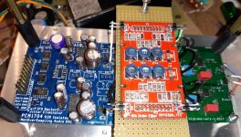
Good evening at the end I connected the 5th order filter of the PHYDAC on my dac with PCM1704 before the I / V. Before this DAC I have had both Buffalo III and Soekris but this PCM1704 is definitely superior. I didn't think I could improve it, but this happened.
Now the sound is cleaner, above all the soundstage has resized has become normal, before it was exaggerated not very real.
A big step forward, now I want to try the 7th order filter.
Thanks Richard
Now the sound is cleaner, above all the soundstage has resized has become normal, before it was exaggerated not very real.
A big step forward, now I want to try the 7th order filter.
Thanks Richard
Attachments
R53 has be removed, the measurements are now:
Across R53: 5.63V
Across R32: 0.0mV
Here my meaning for the voltages was the original test points. I'd like to see if removing this resistor has restored the TPs to their correct values, especially TP1 and TP2.
Here my meaning for the voltages was the original test points. I'd like to see if removing this resistor has restored the TPs to their correct values, especially TP1 and TP2.
All of the following are in reference to TP0:
R53 (terminal closest to board center): 0.367V
R53 (terminal closest to board edge): 6.88V
TP1: 6.94V
TP2: 9.96V
TP3: 5.00V
TP4: 2.49V
TP9: 12.43V
TP10: 11.18V
TP5: 10.11V
TP6: 1.87V
TP7: 3.63V
TP8: 11.69V
Looks like your experiment was correct! Step 1 voltages are close to expected values.
Ah now that's looking quite promising. There is a very slim possibility that the problem's with the capacitor (C22) rather than with the opamp. To separate out those two would you be able to solder back in R53 and lift pin3 of U16 from its pad? If R53 is lost or too badly damaged you could just use a wire in place of it for this experiment. If the voltages with pin3 lifted and R53 back in circuit remain unchanged from those in post #255 then we can safely conclude the fly in the ointment is U16 and not C22.
Good evening at the end I connected the 5th order filter of the PHYDAC on my dac with PCM1704 before the I / V. Before this DAC I have had both Buffalo III and Soekris but this PCM1704 is definitely superior. I didn't think I could improve it, but this happened.
Now the sound is cleaner, above all the soundstage has resized has become normal, before it was exaggerated not very real.
From our past conversations, this PCM1704 DAC was using an OPA861 for the I/V stage. No feedback in I/V right? But now it has a 5th order LC filter between DAC chip and I/V with a matching resistor so that the filter gets the right termination impedance from the OPA861.
The Dac is arrived,,,very fast Thanks
i have just make it to play,,,and will now use some hours just to listen ,and settle in
next will be change the output cap
Best Bjarne
i have just make it to play,,,and will now use some hours just to listen ,and settle in
next will be change the output cap
Best Bjarne
I received mine today. It's smaller than I thought, haha! I hope solder it properly soon.
Thanks Richard!
Thanks Richard!
have first listen to the DAC ,,,and i can say, that i am a bit surprised ,over the sound
very positive ,,,,will now change output cap ,and see if i can get the best out of the output
i also have 3 different powersupply,,,
1..amb .org
2..salas supply (used in his preamp ) this i use now
3..salas shuntsupply
what will you use ??
very positive ,,,,will now change output cap ,and see if i can get the best out of the output
i also have 3 different powersupply,,,
1..amb .org
2..salas supply (used in his preamp ) this i use now
3..salas shuntsupply
what will you use ??
- Home
- Vendor's Bazaar
- PhiDAC hex kits with pre-built filters