Yeah, shoulda bought the ten pack.
I pondered the orientation. Those connectors only give you four keyed choices, I thought that may be the lesser of the evils. May need to reconsider. I’m using bananas myself, but might want to try another type one day. Which way do you orient yours?
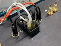
The spades insert into the raised side. i.e. on your red posts, pointed toward your fuse blocks. The channel holds the spade into place and insulates it. So, the spade can't rotate as you tighten it. Super nice for one-hand tightening. Also, if your cables aren't perfectly terminated, it's one more nice measure to keep the outputs from shorting. I also connect and disconnect my speakers quite a bit, so that makes it easier to access when reaching behind the amp with one hand and gives me a bit more peace of mind.
Others find that an abomination and must have their cables come in from the bottom for the cleanest look.
That’s the same way I gathered them to work. I figured to the side might work, so I clocked the insulator to the position you see them in now. But the bottom or top might be better, especially with those cables where the strain relief forces the connectors fairly close together. My AudioQuest RCAs are like that. There’s probably enough room facing down, but up is easier for one-handed operation as you described. Choices...
Last edited:
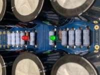
Installed the separate fuse holders for each individual PSUs. Everything clears nicely. However, it turns out if you manhandle a cheap fuse holder, they’ll self destruct. I grabbed the back with pliers to give it that extra little 1/2° twist to get the tabs just so, and BLAM! Fuse holder parts everywhere. So another order goes out and they’ll be here Tuesday. Maybe should have bought the Bussmans, but I was lured into Amazon Prime delivery.
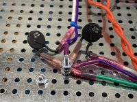
One other thing to note is since I'm planning to elevate the platform to about 1-1/4" (30mm), it places the earth ground lug at the level of the platform. So the lug is bent downward a bit to clear, as you can see in the photo. Solder and heatshrink and it will be well clear. Although there are worse things than ground shorting to ground.
But weird grounds are a PITA to troubleshoot, so might as well head it off at the pass.As the subject of amp noise has been discussed in another thread recently, now would be a good time to consider facing those topics while I’m getting ready to do PSU tests and the case and components are easily accessible.
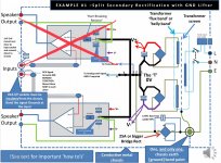
First are considerations surrounding the dual power supplies. Since each PSU is meant to serve a single amplifier board, the level of isolation comes to mind. So considering the attached image below from this ground loop presentation:
http://hifisonix.com/wordpress/wp-content/uploads/2019/02/Ground-Loops.pdf
Should I create two of those environments, each with their own isolation diode bridge, and keep them entirely separated from one another? Or should the power supply pair share a DC output ground between them? Seems like that could cause problems if one PSU were to fail in some spectacular way forcing current through the other. Can’t draw a picture of that idea in my mind at the moment, but just pondering the concept. What I do picture in my mind is two of that diagram (minus one amplifier board, of course).
And, of course, the consideration of providing the audio and DC ground isolation resistors as a preemptive measure.
Attachments
Last edited:
Decided to skip the diode bridge noise isolation technique until it’s needed. Simple is better.
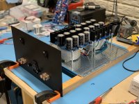
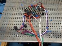
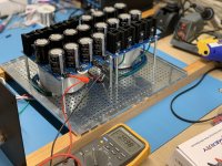
Now everything is (temporarily) wired up and ready for PSU testing. I’m using all the suggestions gathered from each of you commenters, so thank you!
Let’s see how it goes. Fingers crossed...
Things will get cleaned up when the case goes together.
Now everything is (temporarily) wired up and ready for PSU testing. I’m using all the suggestions gathered from each of you commenters, so thank you!
Let’s see how it goes. Fingers crossed...
Things will get cleaned up when the case goes together.
Attachments
-
 4CFF28AD-8BE5-4E42-A0E9-4BA928CCFD63.jpeg724.3 KB · Views: 182
 -
 6D9E4A21-BB16-41BA-B995-DCFA0F016327.jpeg692.3 KB · Views: 171
 -
 11BF5357-6AE2-45E9-84E4-F4AAE0B74CFB.jpg993.7 KB · Views: 166
 -
 B52C8662-0CBB-40D9-8A95-055E32F5C8DA.jpeg894 KB · Views: 166
 -
 7F29C65E-4F85-4BD3-9883-7EFC33DC2E92.jpeg730.3 KB · Views: 138
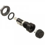
For safety, connect the live wire from the IEC connector to the end connector of the fuse holder. Then when the cap of the fuse holder is off, the exposed ring at the opening of the fuse holder is not live.
Thank you for that safety advice! I will be sure to change that.
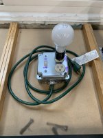
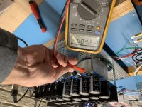
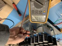
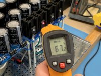
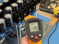
Aside from Ben’s safety advice, the first run of both power supplies was successful! All voltages good, everything running cool.
Attachments
-
 FDC8B483-E6DD-48DF-BDD9-55625ED16187.jpg785.4 KB · Views: 103
 -
 943EAB22-D00B-4D38-8EE7-1402B0A322FA.jpg984.5 KB · Views: 103
 -
 7B3A061B-4F53-45EE-A517-14CE7A5EE9DC.jpg945.7 KB · Views: 91
 -
 6E8A71AE-0FDE-480C-881C-E69B6531F23C.jpg715.4 KB · Views: 96
 -
 E899DCC2-5E79-436B-B5CC-8B00D79A4683.jpg791 KB · Views: 98
Another thing, for low noise and radiation, pair and twist the live and neutral AC wires to each transformer primary, not pairs of live and neutral.
Thanks for another great bit of advice. I’ll work on that as well. You folks are rock stars.
Ben’s comments are spot on but I will say Chris, if this is your 1st time building, your organization and neatness are absolutely excellent. I also like how your chassis ground connection looks serious and is isolated. Far too many times I see diy’ers use the center transformer bolt or more commonly the screw that holds the IEC as the chassis ground. That isn’t recommended especially if the amp needs repair and the technician had unscrewed the IEC for some reason, well then, he/she also defeated the chassis ground which isn’t safe.
Keep it up!
Best,
Anand.
Keep it up!
Best,
Anand.
Hi Anand,Ben’s comments are spot on but I will say Chris, if this is your 1st time building, your organization and neatness are absolutely excellent. I also like how your chassis ground connection looks serious and is isolated. Far too many times I see diy’ers use the center transformer bolt or more commonly the screw that holds the IEC as the chassis ground. That isn’t recommended especially if the amp needs repair and the technician had unscrewed the IEC for some reason, well then, he/she also defeated the chassis ground which isn’t safe.
Keep it up!
Best,
Anand.
Thank you for the kind words and encouragement! I’ve really enjoyed this project. I’ve probably sat and stared at the thing 3-4X longer than I’ve worked on it, making sure that what I’m doing makes sense. I teach device service in the medical electronics industry, and I’m striving to make this device safe, serviceable, and neat. I have to practice what I preach.
. And I’m thankful for this audience when they catch me violating that!Moving on up!
Last edited:

Hey Chris, what is the white wire coming out of the power supply connector block ?
Where does it go ?
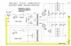
As mentioned, it's the DC return to earth ground via CL60. If you follow the white wire down the post holding up the PSU board (kind tucked up under it, but you can see it in the photo), it passes through the plate grommet. Turn the machine over (in your mind
) and follow it beside the purple transformer drain wire. It will go through a CL60 thermistor and then to earth ground.Is it required for testing? I'd say no. But since the PSUs are in their final position, I wired them in while I was doing everything else.
Edit: In the attached FW PS schematic, it's the section highlighted below.
Attachments
Last edited:
View attachment 935578
Well, clearly my meme editor game is not up to snuff. That was supposed to say Looking Good, Chris...
Ha! Message received, loud and clear! As Bartles and James would say, "Thank you for your support!"
Last edited:
- Home
- Amplifiers
- Pass Labs
- New Aleph J builder from Wisconsin, USA