Yes Minek, I tried Mouser and saw it avail but the datasheet indicated it was obsolete.
However, many others obviously work, and it's good to hear the slot in nicely!
Amused that all of them worked the same....... yet, you think the amp is very good. I would assume that is because it performs flawlessly as the wire, when most amps show issues.
However, many others obviously work, and it's good to hear the slot in nicely!
Amused that all of them worked the same....... yet, you think the amp is very good. I would assume that is because it performs flawlessly as the wire, when most amps show issues.
More stable
The extra gain in the quasi can be a stability issue so I decided to replace the cascode with a static voltage offset. However I then ran into a nasty phase reversal on negative clipping. This happens when the PNP driver saturates and the collector becomes forward biased, allowing the VAS to pull the gate down instead of up. This will be a problem on any quasi MOS.
So my solution is to pad the PNP driver both in and out so that it never saturates, at least not before M2 saturates. You could do this enough so that there would be no need to offset the gate voltage but I suspect that would compromise noise and distortion? Those are the main points.
Attachments
speed vs feedback
Depends on the LTP current. I'm sure it's not as fast as a folded cascode VAS but fast enough for full power at 20KHz. You can reduce C1 provided you also further reduce the feedback and it also effects the VAS output impedance ie "pole splitting". An alternative to degenerating the LTP is increasing C1. It's a trade-off between THD at lower frequencies vs slew related distortion.
Depends on the LTP current. I'm sure it's not as fast as a folded cascode VAS but fast enough for full power at 20KHz. You can reduce C1 provided you also further reduce the feedback and it also effects the VAS output impedance ie "pole splitting". An alternative to degenerating the LTP is increasing C1. It's a trade-off between THD at lower frequencies vs slew related distortion.
How many different audio/electronics forums do you guys have in Russia? 🙂
Looks like this thread can go forever..
So many different variations.. some of them resemble what Maxim shown us before..
Looks like this thread can go forever..
So many different variations.. some of them resemble what Maxim shown us before..
Last edited:

Thank you minek123. During the repair process, I found that the adjustment of his high and low frequencies was not very large
Last edited:
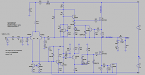
I checked out this JVC amp.
Basically it's simplified (I know, it looks more complicated) version of the LMK amp from the 1st post of this thread.
Differences:
1) it has tone control plugged into the feedback loop (common among cheaper Japanese amp from that era)
2) instead of the current source (Q3/D7 in LMK amp) it has resistors + bootstrap.
3) it has single slope current limiter in the output stage
4) of course it doesn't have germanium transistor in bias spreader, but just standard Vbe spreader
All in all, it's the same amp with slightly inferior bootstrap replacing current source.
Thank you minek123. During the repair process, I found that the adjustment of his high and low frequencies was not very large
Feedback controls can cause amplifier instability. Therefore, the adjustment is shallow.
Mr. Minek123, have you simulated JVC amp? Please upload the simulation file, I will try to modify the JVC amp
Feedback controls can cause amplifier instability. Therefore, the adjustment is shallow.
Thank you Mr. OldDIY, I am considering removing the high and bass adjustment part and modifying the circuit
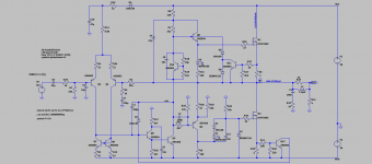
Add emitter follower
Imitate JVC amp to increase emitter follower


View attachment radio_1987_09_elvee_silicon-Emitter follower.asc
Imitate JVC amp to increase emitter follower
View attachment radio_1987_09_elvee_silicon-Emitter follower.asc
Yeah, there were several amps using this topology, including many of them in Russia. I'm sure it has its pros and cons, just like everything else..
The difference between the LMK amplifier and the JVC amplifier is in the use of the RRC correction circuit in the nested OOS
- Home
- Amplifiers
- Solid State
- Unusual amp from 1987