Yeah, it's not bad Mark, but its not great. True though, I guess it must be able to meet spec. presumably that also means you can get better than datasheet performance, without herculean effort.
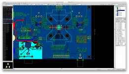
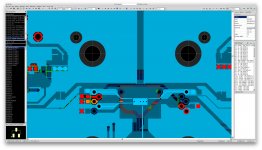
@proid indeed, those decoupling caps are a LOOOOOONG way away. the whole power supply situation seems a bit half baked, but yes, its an eval board, for a low power mobile DAC chip, which happens to perform rather well given those constraints..
@proid indeed, those decoupling caps are a LOOOOOONG way away. the whole power supply situation seems a bit half baked, but yes, its an eval board, for a low power mobile DAC chip, which happens to perform rather well given those constraints..
Attachments
Are someone designing their own ES9038 board here?
It seems there are only cheap boards on ebay or quite expensive dacs.
It seems there are only cheap boards on ebay or quite expensive dacs.
Are someone designing their own ES9038 board here?
It seems there are only cheap boards on ebay or quite expensive dacs.
Quite expensive? you can find Topping d10S for about €80 on aliexpress, excellent measuring and IMD hump free implementation using OPA1656 for IV.
The Topping DACs are quite modding friendly too.
Khadas board is pretty cheap too but obviously not mod friendly.
Last edited:
Thank you a great suggestion.
I have now a ES9018 dac built together with a preamplifier and zapfilter 2 as IV stage.
Diyink isolated Xmos216 chip.
Do not know if topping XU208 is as god soundquality.
My plan is to take the PCB out and put it into my existing rack size case and change all power supply.
Or maybe buy a AK4497 or another PCB from DIYink.
Can you guys come with more suggestions?
Best regards
Last edited:
Are someone designing their own ES9038 board here?
I believe at least one participant in this thread is working on a ES9038Q2M board design.
I got a board marked VR1.07 from this link, though the product image shows VR1.06. Does anyone know the differences in this new version? ES9038 Q2M DAC DSD decoder board supports IIS DSD 384KHz coaxial fiber DOP|Home Automation Kits| - AliExpress
I'm also curious about the display and potentiometer i2c modules it can optionally take and what the actual display is. I tried an ssd1306 I had lying around and it didn't seem to do anything.
sajattack,
IIRC, there may have been some minor changes to board between 1.06 and 1.07. Again IIRC, the most significant change that came with 1.07 was support in the firmware for remote display and remote volume control. However, at about the same time it turned out that remaining 1.06 boards were also being shipped with the new firmware. So, displays and remote volume could work with either version. Maybe someone else remembers its a bit differently, if so maybe they can chime in.
Regarding display modules, I don't recall anyone getting any displays working other than the one specifically sold along with the dac boards.
EDIT: Although a lot of people were interested in building dac board in a box with power supply and having remote control capability for it. Cute idea except that the dac boards really need hardware modifications to sound decent. After modifying the hardware eventually it becomes easy to hear that dac chips sound better if the I2C programming is changed to reduce DPLL_Bandwitdth as much as possible (as ESS recommends in the data sheet). To do that requires temporarily or permanently taking over control of the dac chip from the dac board's firmware, and using an external MCU to change I2C register data (for example using an Arduino). If the display and remote control is to be maintained in that case, then changing I2C registers gets a little more complicated since control of the dac chip must be returned to the dac board firmware after changing register settings.
Actually, the person who is working on a dac board design has also been working to use Dimdim's user interface software for the project. Hopefully, the person will be willing to talk about it at some point, perhaps depending on how things turn out over time.
Last edited:
Hello,
I have adapt DimDim's program for 9038PRO to work with a 9038Q2M. All credit to DimDim and thanks to Mark for all the help.
If someone is intrested let me know. I hope that's ok DimDim? Otherwise let me know..
Changes had to be done to get the program to work with Q2M chip.. there are still bugs but overall it's working ok and plays music 🙂
Most parameters are possible to set, DPLL, Lockspeed, +18db Gain… etc.
Biggest bug right now is that looses lock when changing input very fast in a row..if you change in a slower speed it's ok. Since original program uses GIPO4 as output to check lock I "stolen" other code to check register every second to see if there is a lock. Could be something wrong there…Only a problem if you "trigger happy" with input.
I did some update to use GIPO2 (coax in) as output and read lock there, but haven't upload or resolder the PCB to get it to work.
Program uses Arduino Due and a 3.5 screen.
BR//
Daniel
Would the arduino stay connected and basically become part of the DAC?
Im wondering what is the smallest, simplest chip/solution to just initialise the DAC and set a few of the registers on power up.
Im wondering what is the smallest, simplest chip/solution to just initialise the DAC and set a few of the registers on power up.
Can someone suggest a fairly simple/practical 1kHz bandpass filter to use with this ES9038Q2M DAC for the purpose of testing an ADC with a cleaner test signal?
I am working on repairing/restoring two multichannel interfaces that have nice ADC chips and I thought that this ES9038Q2M with a bandpass might be a suitable cleaner test signal. Does this make sense?
Right now I am using the CS4398 inside one of the interfaces as a test signal however the AK5394 ADC in that interface is as good (or a bit better) so that is not the best test configuration. For example, I get between -113.0 to -122.3 dB second harmonic depending on the channel for the six different CS4398 outputs but the six different AK5394 inputs range from -116.6 to -122.2 dB. So I would like to use a bandpass filter (if that makes sense) to improve the capability of loopback testing of the ADC. For testing the DAC I will use the Hall notch filter.
I am trying to figure out the mystery of why one half of a CS4398 measures -113.6 dB while the other half measures -121.7 dB. There are several channel pairs (which share the same CS4398) that have a big difference between the two sides of the same CS4398 chip. The layout looks nicely symmetric so I don't think that is the cause. So the first step is perhaps to improve the measurements to make sure they are really valid. The ADC are more uniform but there are two channels which are not as good as the other four.
Im wondering what is the smallest, simplest chip/solution to just initialise the DAC and set a few of the registers on power up.
Reprogramming or replacing the onboard processor.
Kozard,
What many people do is order an ultra-low distortion oscillator board from Victor. IIRC the oscillators typically measure around -140dB distortion or a little better. They need a power supply and a case to finish off a build. Prices are very reasonable for such a device. Victor can be reached by forum PM, username: vicnic 🙂
I have one of the oscillators made to order at 1kHz. Tuned my notch filter to match my particular oscillator.
EDIT: Regarding CS4398, the datasheet shows a rather unusual recommended output stage. Don't know why they chose to do it that way, never experimented with the chip myself. Don't know why one channel would differ from the other as you describe either. Seems rather odd.
EDIT 2: Cirrus AN48 is referenced in the dac datasheet. App note attached below. Looks like a typical differential multi-feedback output filter to me.
Attachments
Last edited:
When I made the Hall notch filter I did not think I would need the bandpass output. I could make another with the bandpass output I guess.
How well do you think the bandpass output of the Hall notch filter would work for cleaning up the ES9038Q2M output to serve as a low distortion test generator? Right now I am using LM4562NA in the Hall notch filter.
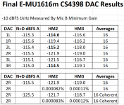
Attached are the results of the six repaired channels of the E-MU 1616m (CS4398). ADC is AK5394. That is what I am using right now for testing. Three CS4398 halves are markedly better than the other half of each chip. [Repair consisted of first repairing two dead power supply sections and then replacing and upgrading over 50 dried out low quality capacitors. Over 30 on one PCB and over 20 on the other PCB.]
How well do you think the bandpass output of the Hall notch filter would work for cleaning up the ES9038Q2M output to serve as a low distortion test generator? Right now I am using LM4562NA in the Hall notch filter.
Attached are the results of the six repaired channels of the E-MU 1616m (CS4398). ADC is AK5394. That is what I am using right now for testing. Three CS4398 halves are markedly better than the other half of each chip. [Repair consisted of first repairing two dead power supply sections and then replacing and upgrading over 50 dried out low quality capacitors. Over 30 on one PCB and over 20 on the other PCB.]
Attachments
Last edited:
Regarding using the bandpass output of a Hall notch filter to filter a dac output, it depends on the spectrum of the dac output, the depth and Q of the notch/bandpass, and whatever distortion and noise the Hall filter components add.
To some extent you can tune a Hall filter fairly easily, but if you want the frequency response to be pretty flat from the 2nd harmonic and up, then the notch using the schematic I posted gives around 38dB attenuation of the fundamental. Bandpass would presumably be about the inverse of that with harmonics attenuated by the same 38dB factor.
To some extent you can tune a Hall filter fairly easily, but if you want the frequency response to be pretty flat from the 2nd harmonic and up, then the notch using the schematic I posted gives around 38dB attenuation of the fundamental. Bandpass would presumably be about the inverse of that with harmonics attenuated by the same 38dB factor.
Does it make any sense to look at component matching in an attempt to understand why one channel of a DAC is -121 dB HM2 and the other channel is -115 dB? I am curious as to the cause.
I replaced the dried out old electrolytic caps, measured, replaced them again and measured again. That does not appear to be related to the channel to channel variation since after the big improvement from the first replacement the measurement results were very stable after the second replacement.
Since the two channels share the same DAC chip I guess I have the filter caps, resistors and opamps left to consider?
By the way the DAC and ADC are all balanced.
Last edited:
Maybe be some funky solder joints too. Don't know. Guess you will have to try some things and see what happens.
Perhaps I will try using the 5 digit DVM to measure the resistors as best I can. And inspect it some more. Then decide if I want to try upgrading one channel pair to OPA1612. (In case it is the opamp. After ten years of service in a studio I wonder if there is any chance of ESD induced issues?)
Matching is fairly important for current output DACs in the I/V stage, right? Is it as important in the filter stage of a voltage output DAC?
Matching is fairly important for current output DACs in the I/V stage, right? Is it as important in the filter stage of a voltage output DAC?
- Home
- Source & Line
- Digital Line Level
- ES9038Q2M Board