When designing SMPS there is always a balance between using a very fast transistor and the noise generated by the switching actions.
You need to check the fall times of the mosfet driver in the controller, you need a relatively fast fall time at the capacitive loads of the mosfet. If the controller is too slow the fet will take too long to switch from on to off. And at that point in the cycle there will be significant current draw if the fet transisitions from saturation to open, it will conduct in its linear region for a while.
Say the fet switches a 24V bus, and the controller senses that it has to switch off at 20A. The fet will dissipate 240W for a very short time during the cycle. How long this time is depends on the switching speed of the FET and controller.
The way flybacks work, is that the transistor turns on, then the current trough the inductor will build up till the controller senses that the current has reached some value somewhere below the saturation current of the inductor.
At this point the current draw is maximum, normally controllers sense the magnitude of the error and modulate the PWM accordingly, otherwise your controller would continiously send bursts of PWM to the FET. And this is inefficient as bursts at close to 100% duty cycle have far greater switching and conduction losses in the FET.
Some transformer manufacturers specify the saturation current for the transformer, others give you a volt/time product. Both can be used to calculate a flyback.
Linear technology makes very good controllers, but you can achieve the same results with UC3843 for example, and that one is only a fraction of the price.
The IRFP devices you have selected wont survive in this application i am afraid, sometimes its better to take a FET that has a higher Rsdon but lower fall times, because the switcher can switch those more quickly.
Furthermore a significant portion of the output voltage is reflected back into the source of the FET, so im afraid a 200V rated device may not be enough.
Case and point: at the frequencies we are talking about here: Conduction losses due to the 10A RMS in your FET are the least of your concern, these are far smaller than the losses incurred in switching off the fet rather slowly.
I am also working on another project for a switchmode bias supply for tube amplifiers, and the FET i have selected for that job is : C3M0280090D
Cheers,
V4LVE.
Last edited:
The IRFP is simply the mosfet that I had in LTSpice (I need to add more definitions) for the initial run (I didn't realise it would take this long).
Your input has got me thinking they've paralleled "VISHAY SUP33N20-60P 200V, 33A NMOS" however I've just not got around to looking much more at the components themselves. The mosfet they've used is obsolete (just did a quick check on mouser). Your suggestion seems faster too but 280mOhm, the vishay is ~60mOhm Ron IIRC.
Your input has got me thinking they've paralleled "VISHAY SUP33N20-60P 200V, 33A NMOS" however I've just not got around to looking much more at the components themselves. The mosfet they've used is obsolete (just did a quick check on mouser). Your suggestion seems faster too but 280mOhm, the vishay is ~60mOhm Ron IIRC.
Last edited:
I forgot to say thank you - I will have a look at the TL783 once this model has got the LT3080 regulation to B+ voltage so I can see what the noise looks like.
Looking at Tom's schematic one point that I can see is that the 3080 is used in 1.34V dropout mode, there's also a second mode which gives something like 340mV drop by having the control above the input (IIRC).
Looking at Tom's schematic one point that I can see is that the 3080 is used in 1.34V dropout mode, there's also a second mode which gives something like 340mV drop by having the control above the input (IIRC).
3080 is a bit of a finkey device, if you put a 47V 5W zener over the 783 it will last a lot longer i think.
Also look at my schematic, you can use a 47-100uH filter after the first capacitor to get rid of the switching harmonics, and clean up the FM interference with 1206 inductors.
Also look at my schematic, you can use a 47-100uH filter after the first capacitor to get rid of the switching harmonics, and clean up the FM interference with 1206 inductors.
I dont think you need the kelvin source connection. A normal 247 package device will do just fine. If you design this into a board your stuck with a non-standard package.
So the mode is 6.8 seconds in.. 68GB..

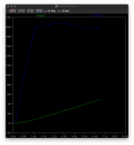
A nice flat curve out of the LT3751 (blue) and the LT3080 is still soft starting (green).
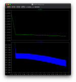
A close up of that flat section shows:

That blue line is after the 6mF cap, it shows the 30-40mV ripple, and more interesting a drop - indicating possibly that the regulation isn't providing enough power. If this is the case then it would result in a slow ripple yet large caused by charge->regulation->charge->regulation->charge->... cycle.
The idea of testing the LT3080 is to see what noise rejection and high frequency filtering it provides. The SMPS I have in mind to perform the 240-24V has a 150mVpp ripple rating by itself.
I can then test this possible power problem after, removing the LT3080 and simply running it with a load, ignoring the ripple but looking at the longer term behaviour.
Given I'm at 6.8 seconds and 68GB.. 10GB/second.. that's going to be 300GB.. for 30seconds of sim time.. this drive only has 190GB free at the start of the sim.. so it's probably not worth waisting the time as I'll run out of disc space and switching to investigate the problem mentioned previously.

A nice flat curve out of the LT3751 (blue) and the LT3080 is still soft starting (green).
A close up of that flat section shows:

That blue line is after the 6mF cap, it shows the 30-40mV ripple, and more interesting a drop - indicating possibly that the regulation isn't providing enough power. If this is the case then it would result in a slow ripple yet large caused by charge->regulation->charge->regulation->charge->... cycle.
The idea of testing the LT3080 is to see what noise rejection and high frequency filtering it provides. The SMPS I have in mind to perform the 240-24V has a 150mVpp ripple rating by itself.
I can then test this possible power problem after, removing the LT3080 and simply running it with a load, ignoring the ripple but looking at the longer term behaviour.
Given I'm at 6.8 seconds and 68GB.. 10GB/second.. that's going to be 300GB.. for 30seconds of sim time.. this drive only has 190GB free at the start of the sim.. so it's probably not worth waisting the time as I'll run out of disc space and switching to investigate the problem mentioned previously.
Last edited:
Hi nick, can i give you some advice?
simulations are meaningless unless you have optimized the circuit on the back of a napkin.
https://www.eetimes.com/power-tip-4...od-alternative-to-integrated-mosfet-drivers/#
simulations are meaningless unless you have optimized the circuit on the back of a napkin.
https://www.eetimes.com/power-tip-4...od-alternative-to-integrated-mosfet-drivers/#
Hmm was trying to load load the LTspice models for the mosfets All Models | Wolfspeed
However what a complete farce of a company - they don't allow gmail - only company or university email addresses to download the models and they only allow this if you tick you want that address to be spammed. Sorry but welcome to the 1990s. Idiots.
So I won't be using that company.
However what a complete farce of a company - they don't allow gmail - only company or university email addresses to download the models and they only allow this if you tick you want that address to be spammed. Sorry but welcome to the 1990s. Idiots.
So I won't be using that company.
There is no point in using spice to simulate snubbers, cause in reality you can approximate somewhat. but once you lay out a board, trace inductance and a boatload of other factors come into play.
Top278 datasheet is very thorough, and shows a example board design with all the components people normally forget
I understand what you think about Wolfspeed. bot on the other hand if loads of people start using their parts the wrong way it could hurt their reputation
Top278 datasheet is very thorough, and shows a example board design with all the components people normally forget
I understand what you think about Wolfspeed. bot on the other hand if loads of people start using their parts the wrong way it could hurt their reputation
Also appears that mouser.co.uk is offline (not authorised ie denial of service attack).
Hmm.. curse of the power supply! lol.
First job is pair back the design, and find the right switching fet. then I'll worry if things need adding to be honest.
Access Denied
You don't have permission to access "http://www.mouser.co.uk/" on this server.
Reference #18.84421202.1615041919.180a5772
Hmm.. curse of the power supply! lol.
First job is pair back the design, and find the right switching fet. then I'll worry if things need adding to be honest.
So napkin style. Given the Ipk is given for the coil craft transformer as 50A at 12V, or 25 at 24V, we see the following formula for the peak given by the application design:
Ipk = 2*Poutavg/efficiency * (1/Vtrans + Nturns/Vout)
or 12.5 / 20.0416 = 623.7mA @ 200V at 100% efficiency. Even at 85% efficiency that's 530mA at 200V.
The Iavg for the NMOS comes between 5.3A (240V) and 7.5A (500V) depending on the voltage output being used.
Now the reflected energy when the diode stops conducting is 0.5*Csec*Vout^2 but .. I don't have that secondary capacitance, calculating it depends on the design from winding angles to layout and if a shield is used. Coilcraft don't give it as a parameter on the data sheet.
Not only does this add to the voltage that the NMOS has to cope with it also adds propagation time as it takes time for the current to drain from the rejected energy.
I'm thinking Capacitance = 1/ 4PI^2 (78KHz * 10 * 2.5uH ) using the switching frequency which IIRC is about 78KHz.
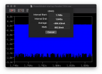
So given per channel we're looking at 2x10+4x25=120mA idle and 2x20+4x60=280mA max then add inefficiencies for a single system through that coil seems a tight squeeze to fit a rounded down 500mA. However that's at maximum transients but it seems a possible option. I have added the LT3751 to the valve amp model. It's likely to draw more power than that and may require a little thinking.
The system is still ramping up (2ch one 10KHz 3.16V, the other 30Hz 3.16V) but..

Last edited:
Theres an interesting Appnote from linear google "Switching diodes switching power supply Jim williams"
AN70 and AN121 are interesting.
Dive deep before you make rookie mistakes(not personal)
PS: UC3845 is ideal for what you are trying to do, because duty cycle is capped at 50% so you don't blow the secondary diode if the supply over-currents. Cheap as chips too. The output stage is quite wimpy however, not really a problem if you use a fast low gate charge SIC mosfet. BUT if people try to repair it in the field and put in a normal high gate charge fet its guaranteed to run WAY hotter than the fast fet you have designed in.
A workaround is to use a PNP over the gate resistor, and a diode to protect the VBE of the PNP during positive going peaks. diode can be a run of the mill MELF 1n4148 FZT1149 is nice for the turn of transistor, but BC807 will suffice in most cases and is faster. You only need that FZT if you where using
If you use a switcher that can do 99% duty cycle. The diode on the secondary side needs to be able to handle all that current in only 1% duty cycle. Then you say: Well use a bigger TO247 skottkey diode: But that is slow AF so it produces a boatload of harmonics and has poor recovery time, so your diode will start ringing like crazy once you increase D beyond say 75% on the primary side.
Too many cheap/Bad SMPS on the marked that have hurt the reputation of a well designed SMPS.
You can indeed use 10uF MKP (Wima DC link is an example) these are rated for such incredibly high ripple currents, they will last forever. The flipside is that they are harder on the diodes sometimes, or may have higher ESL than an equivalent
A well designed SMPS takes all this into consideration, and walks the line between efficiency and noise.
Cheers,
V4LVE
Last edited:
So assuming my calculation of the secondary capacitance is 12.9899nF.
0.5* 0.000000012989935 * 200^2 = 0.000314356434449J per switching event.
78K times a second = 24.519801886990008J/sec = 24.5 Watts of reflected power on average, assuming if this was DC but it's not. so that would be the worst case. (also assuming 200V secondary)
Not sure if that's correct but that would add depending on the design.
Just been looking at nmos that fit the criteria, lots around 600V but 900V starts to become few and far between on Mouser.
Also the gate capacitance and timing figures given in the manual is 3.3nF so at 8V that's 26nC or thereabouts. Also keeping under 120mOhm (preferably 60mOhm) to help reduce time. Annoyingly it appears that the mouser filter is simply providing any random piece but there's an STM piece that may fit the bill 1200V and about £3.50. I'll look at farnell too.
You're right - no computer model will simulate the things sat in front of you. That I am very well aware.
Analog sells an Evaluation Board for this chip -- Digikey carries --
Cool. I think this will be a good starting point. It’s setup for 300V 150mA but it could be adjusted within it’s 10A transformer restrictions.
I’ll allow me to build one channel.
Looking at the pin outs for the TDK (10A on the board) and Coilcraft 20A, although the coils connect different pins, as both sides are tied together there's no difference in phasing or primary/secondary connection. The coilcraft transformer just needs to be rotated.
Not that makes a blindest bit of difference in terms of diode or nmos.
I would say it's a shame that you can't use double secondary coils, 1/2 the current and be able to use lower current diodes but (a) you can't predict the current, the switch point on the diodes etc well enough given manufacturing differences.
Also it looks like the author of that tube project had an issue with the rubicon caps and heat - which makes me think the diode is getting hot but a the use of a single 330V 400uF cap will probably do with splitting into parallel.

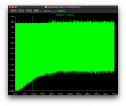
This is interesting on the secondary side - it's showing the current*voltage, negative is the normal current draw, positive showing the reverse current of the diode and secondary capacitance which is giving about 40W.
So in operation that's about 200W with 447mV input. The output is currently stablisizing as the start up bias clamp just released so the amp is starting to take idle current about at about halfway through the plot.
- Home
- Amplifiers
- Power Supplies
- Tube use? 24->300V large cap charger with 300V 150mA reg