What are you people using for power transformer(s)?
I can't find too many torroids with multiple voltage windings so each would probably need is own transformer (5v, 12v and in my case 24-35v)
I see the Antek torroids but they'll cost a small fortune to ship. I've found these Talema's. Any experience with those?
I can't find too many torroids with multiple voltage windings so each would probably need is own transformer (5v, 12v and in my case 24-35v)
I see the Antek torroids but they'll cost a small fortune to ship. I've found these Talema's. Any experience with those?
Cooljazz....I use those talema but in the 15 to 25va versions. Have put them in an Ian Canada stack. All seems OK. They run a little warm and have noticed small mechanical hum develop after 12 months of use.
@har297
>>If there is no degradation because of this, i would try a bit higher gain may be a 2.7k.
You can use 2.7k. There will be no degradation.
>>If there is no degradation because of this, i would try a bit higher gain may be a 2.7k.
You can use 2.7k. There will be no degradation.
R-Core transformers are very good for DACs and precise audio.
Yes, but I can only find them on eBay or Ali and I'm a bit worried about quality. Any known reputable sources?
audiophonics.fr has some (search for R-Core),
it is possible that these are also from china (or on order)
.. hard to say about the quality of the picture, but they look fine
it is possible that these are also from china (or on order)
.. hard to say about the quality of the picture, but they look fine
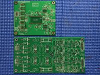
Very nice boards Vunce! Keep us posted.
On your DAC board can you use separate power supplies for each channel?
That is something that I prefer for all my audio projects.
On your DAC board can you use separate power supplies for each channel?
That is something that I prefer for all my audio projects.
No prob Harry, will do.
Yes you can supply the opamps and AD1862/65 chips with separate power supplies (AD1865 is a dual channel chip, can’t separate the psu inputs). Miro strategically placed 0R resistor placeholders along all the power supply traces. Don’t populate those jumper locations and inject your separate power scheme at these points. Be very careful and double check when doing this, it’s a smallish pcb and will get very busy in a hurry with 4 separate analog supplies plus the digital side supplies.
I have powered the opamp section separate from the Dac chip. The reason was for a different voltage (+/-15v instead of +/-12v), not so much a sound quality thing.
Another flexible design by Miro, has anyone got a chance to try this ?
Thanks Miro for sharing this.
Thanks Miro for sharing this.
User @mllum asked for an universal layout for a few different pin-compatible DACs, #1443
PCM56P: 16-Bit; +-5VD, +-12VA (or +-5VA)
AD1860: 18-Bit; +-5VD, +-12VA (or +-5VA)
AD1851: 16-Bit; +5VD, +-5VA
AD1861: 18-Bit; +5VD, +-5VA
AD1856: 16-Bit; +-5VD, +-12VA (or +-5VA)
PCM61P: 18-Bit; +-5VD, +-12VA (or +-5VA)
... maybe another pin-compatible DAC exists
... SB solder jumper on the PCB select between bits, example:
- Short pins 2-3 for PCM56P (16-Bit)
- Short pins 1-2 for AD1860 (18-Bit)
These DAC chips can be considered as a lower cost solution (as they still be cheap). It may surprise with the sound as there are enough of them to test 😎
I don't know much about the sound from these chips, there may or may not be an audible glitch (according to the datasheet it should be neglitible).
Each DAC has 3 pins taked out on the PCB for optional MSB adjustment (-V1, A1, T1, -V2, A2, T2). The adjustment consists of 3 hand-wired parts in series (resistor-trimmer-resistor). This procedure is not very simple, hence optional.
>>...pcb for 8 dac ic's 4 for the left channel and 4 for the right channel
This is not achieved in my PCB due to overall complexity. DAC chips can't be paralleled without decoupling and filtering capacitors. Doing this for 8 chips would significantly enlarge the PCB. Moreover this DAC is not tested if it even works 😀 Check it for possible errors before ordering.
Some people have made parallel chip-to-chip connections, where some pins left unconnected (4, 9, 10, 11, 14, 15) and power pins were decoupled for each chip and connected together underneath - right on the PCB (in this solution a higher digital interference can be present).
Alternatively the 4 same PCBs can be assembled, one with digital glue logic an 3 without glue logic, and all PCBs without opamps - just DACs with capacitors). The first PCB with assembled logic will drive the other three in parallel (BCK, DR, DL, LRCK, GND). The Iouts will be linked together for each channel (here one PCB can act with I/V opamps (R8,R9 value is 1/4 of the value from single DAC) or a passive I/V resistor ... or another I/V solution). Note, that only Iouts shall be linked parallel, not Vouts.
Example list of components (copied from BOM, except some resistors)
mouser:
771-HCT164D652
594-SFR25000Z0000ZA5
C320C104K1R5TA
R79IC3100Z340J
667-EEU-FR1E470
UFG1C471MPM
80-C1206C470G5G
538-87914-0804
575-343308
575-1154731641003000
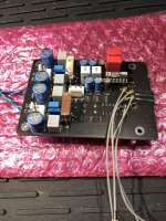
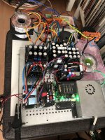
Due to my day job and other projects some time has passed since my last post. But I haven't been totally unactive. 🙂 I've skipped the OP-Amp rolling completly and tried the CEN I/V (J74/K170). Also I separated the shift register from the DAC PCB so that I can plug it on top of the FifoPi and able to use U.FL instead of jumper wires.
CEN I/V works nice with batteries and I really liked the sound. But I was not able to replace the batteries with floating supplies. I've tried 3 different regulator designs but no success - always some hum. So I had to look for alternatives.
I stumbled upon a post fom EUVL about a current mirror based I/V and that's what I use now. @EUVL Great - THX for your generous information, hints and circuit!!
Beside EUVL's I/V I also tried the approach of Painkiller and used stacked separate boards for the left/right channel to overcome the silly placement (and that's putting it mildly) of the digital ground pin of the AD1862 - works fine.
I'm quite happy with the setup now - "only" have to clean up the power supply section before I can install the streamer into a case.
Attachments
Nice work Galac! I’d like to give EUVL’s I/V options a spin also.
Did you populate and use Miro’s pcb at all?
Did you populate and use Miro’s pcb at all?
@Vunce
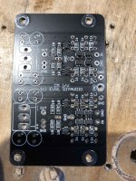
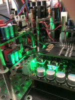
Actually I never tried Miro's design *blush* but my first pcb-version was somewhat close. I only swapped one AD1862 to the bottom so that the digital GND's comes closer and used different sized cap's. Second is w/o the shift registers and incorporates CEN I/V (under the copper heatsinks) as shown in the picture above. Last is the stacked "mono" version.
@diyiggy
Yes and thats not so easy. The two bjt inside the package are super-close matched (8 of 10 are +/- 0/1 or 2 hfe) also the batch is quite close (the difference in 100 npn or pnp is ~ +/- 15 hfe) but as there are no hfe classes the difference between pnp and npn can be very big. First buy from Mouser (npn ~230/pnp ~490), second buy from digikey (npn ~520/pnp ~500).
@har297
No pcb but all the information you need is here A Simple Discrete Current-Mirror IV Converter, à la AD844
Hot op amps
Hello guys and gals
My first test today of checking the rails. I've recently built a Salas shunt reg so thought it a good idea to test on the 12v analogue side. Set the CCS of the psu to approx 130mA thinking that would be ample. Psu fine no load but Once into this dac with op1612 the rails sagged....hhhmm.
Eventually tried with 5532 and the psu rails are all good. But the op amps are hot....35c. Seems excessive. No load on the opamp here. Just the dac board populated and with just the opamps installed as test. Maybe they cool down when asked to actually do something.
I also proved the psu pins to the dac chips and they measure fine so I'll add the 5v rails soon and double check.
Hi Jim,
Power the dac board without Dac chips or opamps to confirm +/-12v and +/-5v are present at their correct sockets and you don’t have shorts or problems with the supplies.
Opa1612 and 5532 are dual opamps and not compatible with this board.
OPA1611 and 5534 are what’s needed.
Power the dac board without Dac chips or opamps to confirm +/-12v and +/-5v are present at their correct sockets and you don’t have shorts or problems with the supplies.
Opa1612 and 5532 are dual opamps and not compatible with this board.
OPA1611 and 5534 are what’s needed.
Last edited:
Hey Vunce. Yes I did a test with sockets empty. All pins measure good.
Ah....I learn something about op amps today then! I have the BOM plus optional opamps on the way from Mouser but they are delayed. I just tried what I had...oops!
Ah....I learn something about op amps today then! I have the BOM plus optional opamps on the way from Mouser but they are delayed. I just tried what I had...oops!
- Home
- Source & Line
- Digital Line Level
- DAC AD1862: Almost THT, I2S input, NOS, R-2R