Thanks Patrick! I am not committed to tube or transistor. Better said, I haven't had anything further to do with tubes. The two best DACs I've had had either a couple of AD1862s or (!) a tube output. I'd like to test both options, find a good way and eventually listen.
I would like to test - especially for the tube - a simple but good one-transistor solution to get the impedance matching right. Calvin talked about a "current buffer" here. However, I got a bit confused in the following... Do you see this as a good solution? If so: could you link me to a good (in your opinion) circuit diagram?
I would like to test - especially for the tube - a simple but good one-transistor solution to get the impedance matching right. Calvin talked about a "current buffer" here. However, I got a bit confused in the following... Do you see this as a good solution? If so: could you link me to a good (in your opinion) circuit diagram?
Maybe a pair of matched D3A with mkp tin foil Output DC blocking from SCR...a laThorsten Loesch ?
It depends on how important to you are :
1) low distortion,
2) DC direct couple.
One of the most famous IV circuit is the one from the late Jocko Homo :
http://www.binatech.se/hem/Amps/i_v.jpg
But this requires an output coupling cap.
Calvin kindly mentioned my CEN IV or SEN IV, but they require unobtanium Toshiba JFETs.
Zen -> Cen -> Sen, evolution of a minimalistic IV Converter
One of your requirements of 20V p-p output makes life difficult for most solid state circuits.
The SEN IV will probably still be as good, due to its working principle.
But you probably need a good 30V floating supply, and good heat sinking.
So if you can make a low distortion, 100x (tube) gain stage with good PSRR and without coupling caps, perhaps you should try a passive IV with 100R R_iv.
First thing to find out is how much distortion the passive IV has before even the gain stage.
If I were to do something like that today, I would probably do it like this (attached), in balanced mode.
But this is only simulation. So you need to build to find out.
And of course what pleases you subjectively, only you can decide.
Patrick
.
Attachments
> Maybe a pair of matched D3A
Yes, a popular solution for passive IV is a phono gain stage to amplifier the signal from a low-value R_iv.
Most solid state IV has a Zin of ~20R, which is of course not perfectly linear.
So a 25R R_iv would not be disadvantageous.
And for 2Vrms out, you would need a gain stage of merely 41dB. 😉
Patrick
One of the most famous IV circuit is the one from the late Jocko Homo :
http://www.binatech.se/hem/Amps/i_v.jpg
But this requires an output coupling cap.
...
If I were to do something like that today, I would probably do it like this (attached), in balanced mode.
But this is only simulation. So you need to build to find out.
.
Thank you again Patrick! Everytime I look into a spice-model I hesitate because of the gray-blue color... 😀
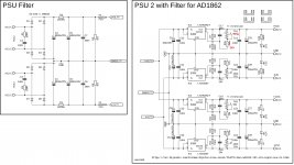
PSU 2 values correction
Hi guys, Vunce informed me about a mistake in the values for +5V in PSU 2.
R15=2k5 and TR1=5k are correct values.
... sorry for any inconvenience
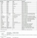
Option 2: Fixed output voltages without trimming:
Trimming part is optional and it may be omitted (R15, TR1, R16, TR2, R17, TR3, R18, TR4). In that case the output voltages are set as fixed and the resistor combinations can be like this example:
R7=1k, R8=320
R9=11k8, R10=36k5
R11=2k94, R12=330
R13=9k, R14=79k6
... attached resistor calculator can be used for those values
... if you find better available values (or with resistors in parallel or series), post it in the forum please (add a note about fixed voltages without trimmers)
Hi guys, Vunce informed me about a mistake in the values for +5V in PSU 2.
R15=2k5 and TR1=5k are correct values.
... sorry for any inconvenience
Option 2: Fixed output voltages without trimming:
Trimming part is optional and it may be omitted (R15, TR1, R16, TR2, R17, TR3, R18, TR4). In that case the output voltages are set as fixed and the resistor combinations can be like this example:
R7=1k, R8=320
R9=11k8, R10=36k5
R11=2k94, R12=330
R13=9k, R14=79k6
... attached resistor calculator can be used for those values
... if you find better available values (or with resistors in parallel or series), post it in the forum please (add a note about fixed voltages without trimmers)
Attachments
So I gave my LME49990  another try now that I have the amplifier that I can actually hear the differences 😀 would LME49990 have more bass and more wide stage compared to ADA4627 and a lot clearer voices?
I am no expert but in my setup LME49990 feels (in a good way) like I just bought a whole new HIFI system. 😱
will get a hold on some more op amps to compare...
another try now that I have the amplifier that I can actually hear the differences 😀 would LME49990 have more bass and more wide stage compared to ADA4627 and a lot clearer voices?I am no expert but in my setup LME49990 feels (in a good way) like I just bought a whole new HIFI system. 😱
will get a hold on some more op amps to compare...
Hi guys, Vunce informed me about a mistake in the values for +5V in PSU 2.
R15=2k5 and TR1=5k are correct values.
... sorry for any inconvenience
Option 2: Fixed output voltages without trimming:
Trimming part is optional and it may be omitted (R15, TR1, R16, TR2, R17, TR3, R18, TR4). In that case the output voltages are set as fixed and the resistor combinations can be like this example:
R7=1k, R8=320
R9=11k8, R10=36k5
R11=2k94, R12=330
R13=9k, R14=79k6
... attached resistor calculator can be used for those values
... if you find better available values (or with resistors in parallel or series), post it in the forum please (add a note about fixed voltages without trimmers)
Does this mean Miro's PS2 board has been validated? If so does anyone have a couple of spares from any of the orders that have already been placed?
... I am no expert but in my setup LME49990 feels (in a good way) like I just bought a whole new HIFI system. 😱
Nice to hear about that Ripster, LME49990 was really great opamp, pity they canceled its production ... they did it with many LM chips (like LM4702 as a nice driver for power amp) 😡
Hi guys, I today received two Rochester's AD1862 more from an american gentleman (Paddy Garcia).
Show must go on, my first old Rochester pair is singing in the Painkiller Diya member's Dac which is a discrete stage from Pedja Rogic I made with (non sorted unluckilly) Fairchild BC550C/560C with a Rhopoint I/V resistor.
Will report after some caps refinment decoupling the oaps I prefer asap in the Miro's 🙂
Excellent news all around, looking forward to reading about your results!
The Rhopoint resistors are made by General Resistance/Prime Technologies here in the US, who were kind enough to break their minimum and send me a pair. Parts for a new power supply are on the way and I'll post my own results once I finish the socketed testbed.
(thread derailment: their minimum is $250, resistors are about $9/each depending on precision so it looks like we could do a group buy with about 14 pairs of resistors. PM me if interested.)


Excellent news all around, looking forward to reading about your results!
The Rhopoint resistors are made by General Resistance/Prime Technologies here in the US, who were kind enough to break their minimum and send me a pair. Parts for a new power supply are on the way and I'll post my own results once I finish the socketed testbed.
(thread derailment: their minimum is $250, resistors are about $9/each depending on precision so it looks like we could do a group buy with about 14 pairs of resistors. PM me if interested.)
Hi
i have a question about the choice of this power supply .
Why this choice LT1963 and LT3015 ?
LT3045/LT3094 are not good pretenders !!
Thanks
Serge
I believe the answer to that question is because lots of DIYers are apprehensive about SMD soldering. But, this technique is here to stay and as more and more THT components go away, everybody will have to learn in order to keep in this wonderful hobby/addiction. 🙂
Hello
because lots of DIYers are apprehensive about SMD soldering
if you use the 1206 SMD format with magnifying glasses it's not very difficult
My opinion
Serge
because lots of DIYers are apprehensive about SMD soldering
if you use the 1206 SMD format with magnifying glasses
it's not very difficult My opinion
Serge
Yes, I agree. You can easily use an iron with a fine tip for 0805 components. I would recommend wearing magnification headgear and a nice set of tweezers.
For not a lot of money, you can buy a hot plate and a hot air pencil station and now you can do almost anything.
For not a lot of money, you can buy a hot plate and a hot air pencil station and now you can do almost anything.
- Home
- Source & Line
- Digital Line Level
- DAC AD1862: Almost THT, I2S input, NOS, R-2R