Have you tried switching the EF86 from the working channel to the other?
Have you also tried running it open loop with the feedback disconnected?
R27 probably should be present as this is in all of the datasheet specs for EF86.
Have you also tried running it open loop with the feedback disconnected?
R27 probably should be present as this is in all of the datasheet specs for EF86.
KatieandDad,
6GC7?
Did you mean 6CG7?
A 6CG7 is similar to an Octal 6SN7, only in a 9 pin smaller bottle (6CG7 is also similar to a 12AU7/ECC82).
The ECC83 is like a 12AX7; much different than a 6CG7.
6GC7?
Did you mean 6CG7?
A 6CG7 is similar to an Octal 6SN7, only in a 9 pin smaller bottle (6CG7 is also similar to a 12AU7/ECC82).
The ECC83 is like a 12AX7; much different than a 6CG7.
To use 6CG7, R9, R10, R11 and R12 would all need to be changed to suit. Using the dynaco improved mullard design, R9 = 22k, R10 & R11 = 62k and then R12 would be adjusted to achieve balance. ~1.8k should be near if you use 62k. I used 68k with a CCS in the tail which negated the need for dissimilar anode loads.
The heater wiring would also need to be tweaked as 6CG7 uses just pins 4 & 5. It either has no connection at pin 9 or an internal shield. (6CG7 & 6FQ7 got merged at some point)
The heater wiring would also need to be tweaked as 6CG7 uses just pins 4 & 5. It either has no connection at pin 9 or an internal shield. (6CG7 & 6FQ7 got merged at some point)
I've just connected R27 (10M), R26 (1K0) & C16 (220pF).
The load resistors are no longer cooking.
I do see a lot of 50Hz ripple on both outputs.
The only difference between my application and the original is that I'm not using CT heater transformer.
The load resistors are no longer cooking.
I do see a lot of 50Hz ripple on both outputs.
The only difference between my application and the original is that I'm not using CT heater transformer.
Last edited:
I think I've found the problem but I don't know what to do about it ?
If I short circuit the inputs at the input sockets, the amplifier is silent on both channels.
If I short circuit the inputs at the input sockets, the amplifier is silent on both channels.

I've just tried it with my existing system and it is absolutely awful with very low volume and horrendous distortion along with massive 50Hz hum.
What are the voltages on EF86 anode, cathode and grid 2? I've found that most issues with this amp almost always pertain to the EF86 misbehaving.
This is what I got with mine back when it followed the correct 5-20 build. It all sounded fine with these voltages. (measured at idle with no input signal)

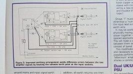
The mains hum suggests a ground loop.
This is what I got with mine back when it followed the correct 5-20 build. It all sounded fine with these voltages. (measured at idle with no input signal)
The mains hum suggests a ground loop.
Last edited:
I did try altering the ground wiring for the input screened wires, changing the screen connection to 0V from one end to the other but that made no difference. The screen is only connected at one end.
With the inputs grounded and 12R load resistors.
LH A = 94V K = 2.36V G2 = 127V
RH A = 102V K = 2.66V G2 = 118v
B+ is 495V
LH A = 94V K = 2.36V G2 = 127V
RH A = 102V K = 2.66V G2 = 118v
B+ is 495V
Last edited:
Those voltages around the EF86 seem a bit off to me. B+ is also a tad high. What voltages do you see across C2, C7 and just after the inductor? If the supply voltage to the first stage are way above 160V, it may well throw things off which ruins the operating point for the direct coupling between V1 & V2.
It would also worth measuring the voltages of the anodes and cathodes on all the other valves to see if they are roughly right or if they also deviate by any significant margin.
It would also worth measuring the voltages of the anodes and cathodes on all the other valves to see if they are roughly right or if they also deviate by any significant margin.
In this application, there is no inductor.
The circuit is too dissimilar to make the measurements that you suggest.
C13 is replaced by 220uF.
B+ to the circuit is 495V.
The circuit is too dissimilar to make the measurements that you suggest.
C13 is replaced by 220uF.
B+ to the circuit is 495V.
Last edited:
For ultralineal would need to drop at least to 450 max for fixed bias but for pentode mode is a good number since your design uses self bias the power tubes Vak will roughly fall under that numbers for a EL34 you can measure the G2 currrent just before clippling if is less than 10mA then I wouldnt worry even a reissue tube will last for long in there.
For a EL34 using 6k6 primary the loadline would look like the following......... the tube is a bit over the 25W limit but since is in the B loadline it would only dissipate that much with a 50% duty cicle so it wont hurt much.
Just dont bias much more than 35-40ma in the class A part of the load it will burden the tube a bit more with 495V you see under no load. 😀
Last edited:
Check FragJanZuerst!Thanks for the pointer to the supplier, but, blimey!, $20, they are quite expensive!
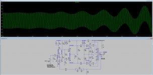
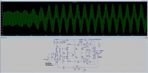
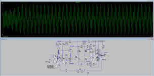
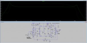
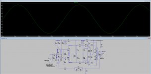
I've plugged the schematic into LTspice and tested it. (ignore the 1K resistor on the grid of V2, I forgot to remove it as my model had it. I've retested with it removed and the results don't change) It looks to be unstable, particularly in the LF. Disconnecting the feedback loop appears to solve the issue but the amount of open loop gain is extremely high. (65dB of gain. just 1mV input gave 14W out) Obviously, the simulation isn't going to be 100% accurate as the output transformer isn't going to match your hammond 1650H but it will give a rough idea.
I'm looking at some component value tweaks that help stabilise the simulation. Dropping the value of C12/C13 from 220uF to 25uF appears to have a fairly substantial effect on it's own. Increasing C9 to 220nF appears to also help. Removing C4 & C5 on the cathode of EF86 in combination with the above appears to virtually remove the LF peak. (down to just under a 1dB rise)
Pictures in order:
1. AC analysis of the circuit
2. 20Hz input at 0.1V
3. 50Hz input at 0.1V
4. 100Hz input at 0.1V
5. 1KHz input at 0.4V
Attachments
Last edited:
- Home
- Amplifiers
- Tubes / Valves
- ETI Hybrid EL34 amplifier