Two SMPS inline DC filters in series !! Cowabunga !
It's delightful that you're pleased with the resulting sound: congratulations.
Thanks, Mark. While I like the larger, complicated projects too, it's nice to have some simpler ones you can put together in an hour or so.
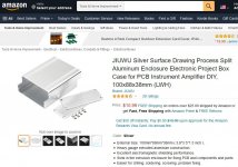
I bought it from Amazon- $11.99. ...I can't seem to get a link to work. ... Jiuwu- Surface Drawing Split Aluminum Enclosure Project Box Electronic Enclosure Case for PCB 88x38x100mm
Amazon Link
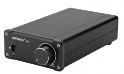
Nice case. That case design style looks like the one for the Aiyima 04 TPA3251 amplifier (other than one being silver and the other black anodized).
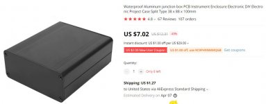
Also this box: Aluminum junction box PCB Instrument Enclosure Electronic DIY Electronic Project Case Split Type 38 x 88 x 100mm


Last edited:
Power Supply Noise Question
I have a pair of Spica TC-60 speakers.
They a not very efficient. 86-87db.
When I plug in an Apple 60w power supply right next to the speaker (like an inch or so) it will hum and the hum will vary in loudness by the task I am performing on the computer. The computer is 3 or more feet from the speaker and this happens with the speaker completely unplugged. No wiring at all.
Just curious.
Dave in MN
I have a pair of Spica TC-60 speakers.....
When I plug in an Apple 60w power supply right next to the speaker (like an inch or so) it will hum and the hum will vary in loudness by the task I am performing on the computer. The computer is 3 or more feet from the speaker and this happens with the speaker completely unplugged. No wiring at all.
Just curious.
Dave in MN
The Spica TC-60 speakers likely have air core inductors in the crossover network which might pickup electromagnetic fields from a poorly shielded power supply.
Spica TC-60 Crossover Schematics
"Inductors
1 – .28 mH
1 – .63 mH
1 – 1.10 mH
1 – 2.07 mH"
Last edited:
Question - I got the needed stuff from Mouser, but the 470uf caps are out of stock (in stock @ the time I ordered), can I substitute with say, 1500uf, from my part box, or should I stick with 470uf?
Thanks!!!
Duc
Thanks!!!
Duc
Overkill, but it can't hurt.
Any decent audio-grade 470uF cap will be fine. Nichicon, Elna, Panasonic, etc.
Any decent audio-grade 470uF cap will be fine. Nichicon, Elna, Panasonic, etc.
Mark went the trouble to define exactly his filter, with given components that are well chosen and proven. That doesn't mean others won't work, but the result might not be the same.
I experimented with a similar filters and bigger caps, hoping it would work even better (lower Fc, lower ESR etc), but not really. Worked, but the real Mc Coy is just that. By Mark.
Claude
I experimented with a similar filters and bigger caps, hoping it would work even better (lower Fc, lower ESR etc), but not really. Worked, but the real Mc Coy is just that. By Mark.
Claude
Short report on the new caps Mark has recommended.
I have built 2 filters with the original caps, and 8 with the upgraded caps (and bought spare caps to upgrade the first ones in case of, trusting Mark on that).
Given I was biased to carry out the comparative test, given most of these filters are to give away except for a few I carry with me or I keep in the B1 Korg, I gave a friend the lastest iteration of this filter.
That friend had already the original filter, doesn't care about electronic, doesn't know the possible differences. He has some dirty PS for his audio where the original filter shone, especialy DACs. He reported the one I gave him as "being very similar, little differences, but... could it be that I hear voices with more flesh, even finer treble and notes that flow better, end not so sharply. That's my quick perception when putting the one you gave me recently instead of the old one I already appreciated and still do".
He asked me if that was some kind of "positive burn-in I played on it"... nope, it is the caps, they are different, all other bits are strictly identical (same parts, same boards, same builder, same soldering iron LOL).
I recommend highly a) you build Mark's excellent filter (no brainer really), b) you do so going for the latest caps he recommended.
I do from now on and will upgrade the old ones I did.
I hope this helps / thanks again Mark, full credit to you
Claude
Predicting whether your device can work with two PO89ZBs in series "daisy chain"
If you have a medium quality (say > USD 50) digital voltmeter, you can try this simple procedure to see whether your audio gear is likely to work properly when TWO of these SMPS dc inline filters are connected, in series, between the wall wart and the audio gear.
However, the procedure does involve arithmetic. If you're frightened of arithmetic, if you often post messages that say "Just want to confirm that I operated the pocket calculator correctly", this is not for you. But if arithmetic doesn't scare you, read on.
Step 1. Connect a single PO89ZB as a filter between the wall wart and the audio gear. Turn on the audio gear and play music through it as you normally would.
Step 2. Use your DVM to measure the voltage between the "IN" pin and either of the two the "GND" pins of PO89ZB. Write this number down in your audio notebook "ALICE = (measured voltage)"
Step 3. Use your DVM to measure the voltage between the "OUT" pin and the "IN" pin of PO89ZB. This will be a small voltage and you may need to adjust the meter's range switch to display it accurately. Write this number down in your audio notebook "BOB = (measured voltage)"
Step 3. Use a pocket calculator (or a pocket calculator emulator on the internet) to perform a division operation. Calculate the number (BOB divided_by ALICE). Write this number down in your audio notebook "CAROL = (division result)"
Step 4. Look at the number CAROL. Is CAROL less than or equal to 0.004? (less than or equal to 4E-3)? Write the phrase "BIG CAROL" in your audio notebook, if CAROL>0.004. Write the phrase "SMALL CAROL" otherwise.
Step 5. If you've got a SMALL_CAROL then it is very, very likely that your audio gear will work delightfully well when you connect two PO89ZB filter PCBs in series, between your wall wart and your audio gear. Try it!!
Step 6. If you've got a BIG_CAROL, your situation is more problematic. Your audio gear MIGHT still work fine with two PO89ZBs in series, but it's less certain. If the number you wrote down for CAROL is less than 0.01, it's worth a try to hook up two PO89ZBs with your audio gear and see what happens. Your gear might be very tolerant and it might work beautifully well. Or not. Could be either one. That's why you're doing an experiment.
Step 7. If you've got a very large CAROL number, nobody really knows what it will do. You don't meet the safety criterion in Step 5. Obviously, as a DIYer, you can Do whatever You like. Certainly I cannot prevent you from connecting two PO89ZBs in series between your wall wart and your gear, then checking what happens. Maybe it will do no damage, maybe it will work. Your experiment, your risk. And I wish you happiness in the pursuit of your hobby.
I am having difficulty finding the posting that gives the information on the new caps recommended by Mark. Can someone direct me to the correct posting or the new cap info?
Thank you I probably missed it.
Thank you I probably missed it.
Couple months ago. I ordered the parts on Pearl Harbor Day. It took them a few days to reach me. Upon delivery I didn't immediately-and-without-delay tear open the box & run some measurements. So: sometime, approximately a couple months ago.
If not mistaken, basicaly saying that for a given device (assuming roughly 0.1R DC filter resistance)
IF : i < "4% of Vin", then 2 filters likely to work better.
Higher ("above" that value), we can't tell...
Much higher obviously not the scope of the device anyway.
Mark, are you implying 2 filters are likely to work with "relatively to voltage small amperages"?
For those having a B1 Korg, you are in the Small Carol case, so 2 filters likely to make sense... may try 2 filters once back in Europe.
Claude
Mouser PSA - if you live in the US and have an order shipping from Mouser's TX facility, they are running slower than normal. I placed an order on Monday and it's still sitting at their warehouse. I'm waiting on my parts to build two boards.
Did the above quick and dirty while waiting for plane.
Assuming correct, is there a reason behind this... other than obviously the filters then leading to very small voltage losses if constant current is drawn... or less fluctuations per se with varying current needs as the overall current is small and its variations even smaller so the resulting voltage fluctuation due to R DC of the filter very small?
Just thinking out loud and posting notes for myself in fact LOL
- Home
- Source & Line
- Analog Line Level
- PO89ZB, an inline DC filter for SMPS wall warts. Preamps, HPA, Korg NuTube, etc