i have seen similar. Some are very good and some vendors are simply poor (maybe good for guitars). my experience is to look for conductive plastic and Bourns has some of the best I have seen. To seriously test them I use two Radiometer CLT-1's since it has no provision for separate source and measure. The wipers are the hard part.
I'm not sure which pots you have. let us know. I may have some I can test.
I'm not sure which pots you have. let us know. I may have some I can test.
The two pots must be minimum-distorting. They are easy to measure - switching to a soldered resistor divider as DUT (basically zero distortion) must not raise the pot-calibrated distortions. Not all pots made the test, only 50% success so far. One had slightly elevated H2, the other was plain bad. I will see what the stats will do with the next batch waiting in transport.
These are DAC-side distortions calculated from combined distortions and LPF transfers measured with pot 1 and pot 2 (those with same distortion as the soldered divider, used in the adapter).
Would be interesting to see some of the older variants of the 5532 opamp as there are rumors to be better.
Demian: The pots are "Bourns" 10-turn wire wound 3590-S2 from ebay. They look exactly same as in Bourns original datasheet. I looked inside, again same construction as videos on youtube. The key difference is price - Bourns from Farnell costs 15USD while the ebay one is 1.40USD. I think they come from the same factory, I do not think a market for these specialty pots is so big that someone would design and manufacture very exact clone (except for cheaper contact coating). Perhaps they are factory rejects of Bourns OEM manufacturer, but basically nothing wrong with 3 out of 4.
2 out of 4 were of undetectable distortion in my setup (all harmonics below -140dBr). The third has only H2 at -130dBr which is perfectly suitable for any other task and IMO would pass Bourns performance check easily. The last one is noisy and distorting much more but it is the one I opened - perhaps that is the cause.
Considering the 10x price difference (2x 15USD would increase the BOM cost drastically) I will change my previous adapter make to pot tester and pre-measure the ebay pots before using. Inside they are quite well lubricated to assume the contacts may not deteriorate over time. If so, replacing them would be still way cheaper.
Or several models of the adapter - some with the original bourns 🙂
Vishay Spectrol pots have the same dimensions as S3590 Bourns and cost 35% less. Partly metal enclosure, sealed, the easy-to-solder yellow leadouts suggest the contacts inside are from proper material, they have exactly same color as the Ni-Ag 6.3 TRS sockets by Cliff CLIFF Electronic Components - Professional Jack Sockets S2 used for connecting the sound card.
Two pieces tested so far, the most stable performance of all the pots I have tested. Soldered resistor divider and the pot are undistinguishable after tens of minutes after calibration.
Consistency and repeatability is important. At 10+pieces they cost 6.3USD a piece which is acceptable, pots are the most crucial part of the calibration adapter.
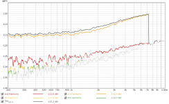
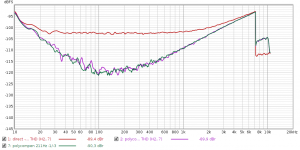
Measuring distortion-compensated DAC output of E-MU 0404 USB on analyzer APx582.
1) compensation off
2) compensation with continuously running calibration/distortion splitting
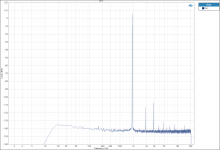
3) APx582 loopback at the same frequency and level (not compensated, of course)
The analyzer loopback (i.e. AP DAC + AP ADC) is clearly above compensated EMU DAC + AP ADC, while the uncompensated EMU DAC peaks high above both.
1) compensation off
2) compensation with continuously running calibration/distortion splitting
3) APx582 loopback at the same frequency and level (not compensated, of course)
The analyzer loopback (i.e. AP DAC + AP ADC) is clearly above compensated EMU DAC + AP ADC, while the uncompensated EMU DAC peaks high above both.
Attachments
Pavel that is an almost 20dB improvement, very worth-while.
Do you know what limits the maximum improvement you could get? Is it phase noise?
Jan
Do you know what limits the maximum improvement you could get? Is it phase noise?
Jan
Actually IMO a large portion of the remaining measured distortion is the ADC-side distortion of the AP. I conclude from the fact that the LP filter path worsens the harmonics just by a few dB (e.g. from -142 to -138dB) in my measurements compensated on both sides, even though it rotates the harmonics by many tens of degrees. Such large rotation of a 120dB harmonic would produce much larger change when subtracting from the calibrated value than from -142 (voltage divider - calibrated) to -138dB (LPF - rotated).
Further measurements would need a notch filter to eliminate the ADC distortion - just like your measurement of the oscillator. Or the ADC distortion internally compensated by the AP itself, for the 25+ grand 🙂
A major logical improvement would be using a low-distortion hardware in the first place, to not having to start from -100dB H3 like in my DAC. I am really looking forward to seeing results from the RTX.
Also the RC filter could have some ultra-low distortion capacitor (using WIMA FKP2s now). The Vishay Spectrol pots behave consistently very well, there is not much room for practical improvement, unless a different fine-tunable distortion-free attenuation technology was used (I do not know which).
And a major stability improvement I am seriously considering is simply soldering the soundcard - adapter interconnects to avoid the TRS connectors, at least on the adapter side, and using proper Neutrik TRS or XLR on the soundcard side. The reason I have avoided them so far is such connectors themselves cost like the rest of the adapter altogether 🙂
Software improvements can be perhaps playing with FFT windows. Since the beginning I use vector averaging (what REW calls coherent averaging) of 10 FFT measurements, 30 vector averages for measuring the paths transfer at each harmonic frequency (e.g. once a day, before the measuring session), there is likely not much room for improvement. A longer FFT (2xfs) could be used too. All calculations are already in double (64bit float), going deeper makes no sense, IMO.
The compensation performance was measured last week in the perfectly equipped lab of Demian Martin. Getting proper signal from RTX6001 in linux took a few days. The linux USB-audio driver had to be told to work properly with the isochronous async implicit feedback of the XMOS firmware (the patch is already in the upcoming linux kernel 5.8). A hardware fix by Demian to his RTX improved short-term level stability of its output signal by an order of magnitude down to 10^-4 dB, i.e. on par with Juli@ or E-MU 0404 USB.
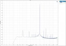
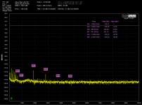
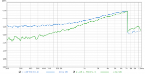
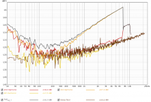
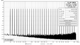
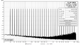
RTX output at 10Vrms full scale (signal 941Hz @ -1dBFs) driving 100R input impedance of the cleansine adapter, the output notch-filtered by Shibasoku 725D set on THD analysis at -110dB range, precisely level-calibrated QA401 analyzing the residua behind the notch filter (32k FFT, 7 averages, flat top window).
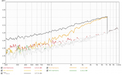
At 9Vrms to 100R load the RTX was quite loaded, producing notable distortion:

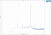
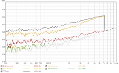
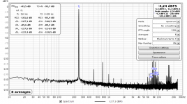
Upon starting continuous compensation the RTX output harmonics changed as follows

In numeric terms:

Clearly the metod in this particular setup calculates correctly DAC distortions down to original level of -140dB, smaller distortions (H6, H10, H8) are below noise for the 4xfs = 192k FFT calibration to calculate correct DAC-side amplitude and phase.
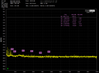
Precision of the 725D -> QA401 relative-level (dBr) calibration is confirmed by comparing harmonics for non-compensated RTX DAC signal measured by QA401 (the first figure) and the split-calculated/compensated harmonics by the cleansine adapter

Measured minus calculated harmonics, the difference expressed in dB:

I would like to thank Demian for his great patience and support. Also thanks to Matthias (mbrennwa) for testing the linux RTX patch.
Code:
RTX output  --> cleansine adapter --> RTX input for calibration
            |
            V
        Shibasoku 725D
            |
            V
QA401At 9Vrms to 100R load the RTX was quite loaded, producing notable distortion:
Upon starting continuous compensation the RTX output harmonics changed as follows
In numeric terms:
Clearly the metod in this particular setup calculates correctly DAC distortions down to original level of -140dB, smaller distortions (H6, H10, H8) are below noise for the 4xfs = 192k FFT calibration to calculate correct DAC-side amplitude and phase.
Precision of the 725D -> QA401 relative-level (dBr) calibration is confirmed by comparing harmonics for non-compensated RTX DAC signal measured by QA401 (the first figure) and the split-calculated/compensated harmonics by the cleansine adapter
Measured minus calculated harmonics, the difference expressed in dB:
I would like to thank Demian for his great patience and support. Also thanks to Matthias (mbrennwa) for testing the linux RTX patch.
Last edited:
Jan, thanks for your support. Actually I really like that we can construct a theory in our mind and when (correctly) implemented, the theory and practical result fit. There is lots of irrational voodoo around us, but the nature stays consistent and reliable, fortunately.
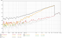
At -12dB output the RTX native distortions are way lower, yet still yield to compensation.
At -12dB output the RTX native distortions are way lower, yet still yield to compensation.
Attachments
Long time no update, but some work done meanwhile.
A new calibration adapter allows distortion calibration/compensation of balanced outputs/inputs. Procedure for the balanced signal calibration is slightly more complicated. It requires a balanced LPF, balanced voltage divider (i.e. with two pots), and relays for independent grounding of + and - input lines of the analyzer. Because + and - paths of every analyzer input distort differently, amplitudes of the calibration +/- signals against ground must be closely similar to those of the LPF output (or DUT output). The adapter/software measures +/- line levels against ground first, and adjusts the respective pots in +/- branches accordingly, so that the voltage divider outputs a balanced signal with the same level characteristics. After that the calibration and calculation of DAC/ADC contributions is identical with the single-ended mode.
SE and BAL results are basically same - DAC/ADC compensated THD -132dB for VD loopback at -3dBFS output signal, dropping to -128dB upon switching the path to the LPF filter. Uncompensated THD -98dB at the same output level.
To buffer the balanced output of my soundcard I added OPA1622 before the adapter output and calibration paths. Since this balanced adapter version is a proof of concept, only crucial parts were installed. To minimize distortion from mechanical contacts the symmetrical cables are soldered directly, and finally proper Neutrik TRS jacks were used (a HUGE quality difference compared to my previous chinese cheapos, zero problem with level or distortion stability). The PCB layout is identical to the previous version to re-use the existing adapter case.
The adapter/SW shows that the distortion compensation works for balanced signals too. The calibration circuitry (especially the feedback and grounding relays), when implemented in a standalone analyzer together with a calibration signal generator using the analyzer's internal voltage reference, would allow other automated SW/HW-based calibration/compensation features - checking balance of input/output dividers (using the +/- input lines grounding relays), precise software-based calibration/compensation of the input and output balanced dividers ranges, checking frequency compensation balance of input divider steps (using the grounding relays), software-based frequency compensation of the balanced input divider ranges, etc. Lot's of work ahead 🙂
Attachments

Last edited:
When coding the balanced version I temporarily limited the number of DAC-side harmonics being calculated/compensated to H2-H4 and IMO an illustrative situation occured. Upon switching from the ADC-calibrated VD to LPF, only the harmonics compensated on the DAC side were kept minimized. The remaining uncompensated DAC distortions H5+ were rotated by the LPF and re-appeared.
The last screenshot is uncompensated performance of the setup.
A simple video showing the DAC/ADC calibration/compensation process and results for all and some distortions compensated on the DAC side DAC/ADC Digital Distortion Compensation - Proof-Of-Concept Implementation - YouTube
The last screenshot is uncompensated performance of the setup.
A simple video showing the DAC/ADC calibration/compensation process and results for all and some distortions compensated on the DAC side DAC/ADC Digital Distortion Compensation - Proof-Of-Concept Implementation - YouTube
Attachments

Last edited:

Thanks for your support, guys.
As for the nickel-based paint - I got a reasonable quote from the Chinese manufacturer (plus the shipping cost which is crazy these days). In the end I stayed with the copper tape for the testing adapter.
I consulted the shielding with a specialist. For a standalone analyzer with built-in compensations a metal enclosure shielding also magnetic fields would be a must. Laser-cut metal sheet, machine-bent, powder-painted - I got several quite reasonable price quotes, the many local automotive subcontractors around help in this regard.
Compensation of static distortions using a transfer polynomial is quite common (e.g. H2 & H3 compensation registers on ESS DACs). I actually started this thread with polynomials. By their nature they can only compensate the static part of the distortion vector. For H2 that would be a component of the actual vector corresponding to the -90° angle - my loopback measures H2 angle at -60° in REW - the static distortions are rotated by dynamic nonlinearity of the chain.
But the polynomials can be applied to any signal. Since the tool already measures harmonics precisely, why not compensating the static distortions with the polynomial, leaving the remaining distortions to the precise single-frequency compensation for single-tone measurements.
It takes just re-generating a pre-distorted signal (i.e. with distortions rotated by 180°), and finding a transfer polynomial converting a precise sine signal to the pre-distorted waveform. I used a piecewise polynomial (splinefit in octave/matlab), fitting a number of polynomials along the <- maxampl, +maxampl> range of samples.
The polynomial was calculated for distortions at 911Hz@-1dB DAC out, analog loopback to ADC through the voltage divider of the compensation adapter.
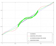
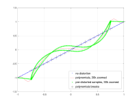
* The first plot shows the fitting piecewise transfer polynomial, at 30k zoom. Axis X is clean input sine, axis Y is the calculated pre-distorted signal. The polynomial is forced to go through at [-1, -1] and [1, 1] so that the compensation behaves OK for samples outside of the calculated range. A strong 3rd order, a bit of 2nd order (slightly bent towards the positive half).
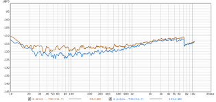
* The next two charts are distortions vs. frequency measured in REW for -1dB@DAC - direct and compensated on the ADC side by the polynomial.
* The next two charts are distortions measured in REW for -3dB@DAC - direct and compensated on the ADC side by the polynomial.
* The last two charts are direct and compensated THDs for -1dB and -3dB@DAC.
The charts clearly show how the dynamic distortions of H3, unaffected by the static polynomial, take over at higher frequencies.
All the measurements are for joint-sides distortions, polynomial-compensated on the capture side. A real implementation would/will use the split-sides distortions, yielding compensation polynomials for DAC and ADC sides separately.
Just for comparison - ESS H2 compensation e.g. at https://cdn.shopify.com/s/files/1/0321/7609/files/DAC3_-_2nd_Harmonic_Compensation.GIF?v=1478880997
But the polynomials can be applied to any signal. Since the tool already measures harmonics precisely, why not compensating the static distortions with the polynomial, leaving the remaining distortions to the precise single-frequency compensation for single-tone measurements.
It takes just re-generating a pre-distorted signal (i.e. with distortions rotated by 180°), and finding a transfer polynomial converting a precise sine signal to the pre-distorted waveform. I used a piecewise polynomial (splinefit in octave/matlab), fitting a number of polynomials along the <- maxampl, +maxampl> range of samples.
The polynomial was calculated for distortions at 911Hz@-1dB DAC out, analog loopback to ADC through the voltage divider of the compensation adapter.
* The first plot shows the fitting piecewise transfer polynomial, at 30k zoom. Axis X is clean input sine, axis Y is the calculated pre-distorted signal. The polynomial is forced to go through at [-1, -1] and [1, 1] so that the compensation behaves OK for samples outside of the calculated range. A strong 3rd order, a bit of 2nd order (slightly bent towards the positive half).
* The next two charts are distortions vs. frequency measured in REW for -1dB@DAC - direct and compensated on the ADC side by the polynomial.
* The next two charts are distortions measured in REW for -3dB@DAC - direct and compensated on the ADC side by the polynomial.
* The last two charts are direct and compensated THDs for -1dB and -3dB@DAC.
The charts clearly show how the dynamic distortions of H3, unaffected by the static polynomial, take over at higher frequencies.
All the measurements are for joint-sides distortions, polynomial-compensated on the capture side. A real implementation would/will use the split-sides distortions, yielding compensation polynomials for DAC and ADC sides separately.
Just for comparison - ESS H2 compensation e.g. at https://cdn.shopify.com/s/files/1/0321/7609/files/DAC3_-_2nd_Harmonic_Compensation.GIF?v=1478880997
Attachments

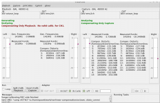
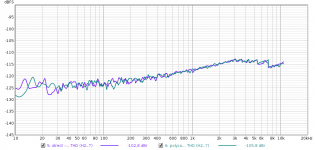
New set of measurements with the voltage divider in the calibration adapter set to minimum attenuation, to raise the ADC level compensated by the polynomial. Frequency sweep from 10Hz to 22kHz.
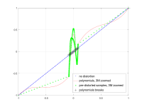
1) The first figure shows the polynomial (red) covering ADC levels to -3dB now, the edges converge to -1/-1, +1/+1, magnified 30k times.
2) Fundamental frequency at which the polynomial calibration is performed is not important - the second picture shows THDs at -1dB DAC/-3dB ADC - direct, compensated at 911Hz and at 211Hz. The compensated THDs are basically identical.
H2 at levels close to the polynomial edge shows a hump - the cause remains to be investigated. The hump is not present at smaller levels.
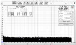
3) direct -1dB DAC/-3dB ADC
4) compensated -1dB DAC/-3dB ADC at 911 Hz (an 211Hz chart is almost identical)
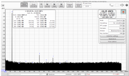
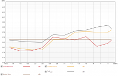
5) THDs at -10dB DAC/-12dB ADC
6) THDs at -20dB DAC/-22dB ADC. At this level the static polynomial compensation has no effect, but does not cause any fake distortions either.
7) Calibrating the polynomial by distortions measured -20dB level makes no difference either, the swept THDs do not change compared to the previous figure. The figure 7 shows the transfer polynomial magnified 3 million times.
IMO the static compensation, when calibrated for a signal close to max DAC/ADC limits, behaves safe for any level and frequency of the signal, both for measurement and musical signals.
1) The first figure shows the polynomial (red) covering ADC levels to -3dB now, the edges converge to -1/-1, +1/+1, magnified 30k times.
2) Fundamental frequency at which the polynomial calibration is performed is not important - the second picture shows THDs at -1dB DAC/-3dB ADC - direct, compensated at 911Hz and at 211Hz. The compensated THDs are basically identical.
H2 at levels close to the polynomial edge shows a hump - the cause remains to be investigated. The hump is not present at smaller levels.
3) direct -1dB DAC/-3dB ADC
4) compensated -1dB DAC/-3dB ADC at 911 Hz (an 211Hz chart is almost identical)
5) THDs at -10dB DAC/-12dB ADC
6) THDs at -20dB DAC/-22dB ADC. At this level the static polynomial compensation has no effect, but does not cause any fake distortions either.
7) Calibrating the polynomial by distortions measured -20dB level makes no difference either, the swept THDs do not change compared to the previous figure. The figure 7 shows the transfer polynomial magnified 3 million times.
IMO the static compensation, when calibrated for a signal close to max DAC/ADC limits, behaves safe for any level and frequency of the signal, both for measurement and musical signals.
Attachments

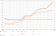
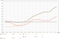
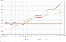
Stepped-sine measurements in REW are trivial, allowing THD vs. level analysis. All measurements use a polynomial calibrated at 911Hz/-1dB.
THD/level measurements at 911Hz - (1) direct, (2) compensated - and 211Hz - (3) direct, (4) compensated.
DIN dualtones with peaks close to 0dBFs - (5) direct, (6) compensated
Multitones with peaks close to 0dBFs (basically same as those used by Amir for ASR reviews) - (7) direct, (8) compensated.
IMO there is no reason not to use static distortion compensation to improve measurements resolution as it requires only a simple software support and works for any signal. IMO it has potential benefits for audio playback/recordig too (likely even audible on more-distorting setups).
Attachments

Hi Pavel,
for a while now I have a running Ubuntu 18.04LTS on a Lenovo E330 which should have enough CPU power (i3-3110M @ 2.4GHz) and RAM (3GB).
RME ADI-2 Pro is running (ALSA direct, Pulseaudio bypassed) and REW is doing fine also.
So now I should be ready to try your excellent approach. I can solder up any jigs required, etc.
Where would I start, exactly? Do have some sort of (condensed) write-up for the required steps to get this running?
- Home
- Design & Build
- Equipment & Tools
- Digital Distortion Compensation for Measurement Setup