4 various 4565s:
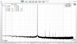
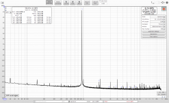
Fig 1 JRC4565 piece 1
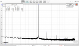
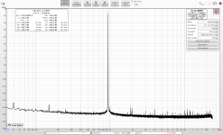
Fig 2 JRC4565 piece 2, clearly both from a similar batch/matrix, ...
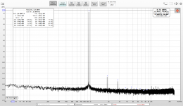
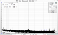
Fig 3 again JRC4565, this looks like a different batch, something fixed in the process
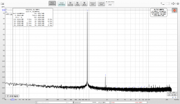
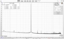
Fig 4 different RC4565 (different manufacturer), similar to the previous one but the H3 is fixed here. Quite decent piece.
Fig 1 JRC4565 piece 1
Fig 2 JRC4565 piece 2, clearly both from a similar batch/matrix, ...
Fig 3 again JRC4565, this looks like a different batch, something fixed in the process
Fig 4 different RC4565 (different manufacturer), similar to the previous one but the H3 is fixed here. Quite decent piece.
Attachments
What is interesting is that some opamps have the spurious 1kHz multiples emphasized, while others seem to ignore it. Some form of oscillations? Maybe the OPA1656 buffer inside the compensation adapter is prone to oscillations, I have not used the 100nF blocking capacitors, only 22uF filtration caps at the opamp power pins.
This guy measured NE5532 in detail http://www.ac-vogel.de/Download/Dow...act, no myths and THD measurement results.pdf . EMU0404 USB headphone output at -1dB will be around 2Vrms - my measured THD -127dB fits the chart quite nicely, IMO
Attachments

Since the OPA1656 THD was undetectable compared to a voltage divider at <-133dB in my measurement adapter with regular non-inverting voltage follower, I changed the OPA1656 buffer inside the adapter to non-inverting, using other opamp half for buffering the cold line of balanced input and keeping thus the balanced connection functional. Slight noise reduction as a result was to be expected.
Next step is testing an isolated USB 5V -> +/-12V DC/2xDC module, to avoid the external power source. For now decided on http://www.farnell.com/datasheets/2...17.278992240.1585684932-1944921956.1583361641.
And then Mk2 with two steppers/pots (LPF level, DUT output level) to avoid retuning the pot and speed up split-sides calibration.
My soundcard + the adapter need about 30 minutes to warm up and have their distortion profile stabilized. Also soldered cables instead of connectors would definitely be a way for best results.
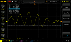
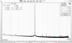
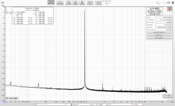
The DC/2xDC converter from arduino USB 5V to isolated dual +/-12V TBA1-0522E with LC filters SMD 150uH (self-resonant frequency 6MHz) + 330nF in each voltage line next to the converter, placed into the shielded arduino compartment, powering the OPA buffer and the opamp measurement adapter (i.e. two opamps). My soundcard is unstable at 192kHz, thus only 96kHz samplerate measurement. The peak at 47kHz is generated inside the soundcard and unrelated to the supply.
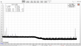
Fig 1: powered by two SLA 12V/7Ah batteries, arduino off (disconnected from USB port).
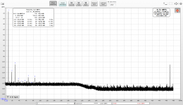
Fig 2: powered by the USB 5V -> DC/2xDC converter
Fig 3: powered by the USB 5V -> DC/2xDC converter, second measurements. The small peaks travel randomly, this time similar to the batteries spectrum.
Result - in 48kHz range the DC/DC converter creates no visible peaks. According to the datasheet it should run at 40 - 200kHz, clearly it does so above 48kHz.
Since generating power for the buffer/measurement adapter/voltages for input protection diodes from the arduino USB is much more convenient than an external dual-voltage supply, this DC/DC converter will be in the new version of the calibration adapter, to be designed now.
Fig 1: powered by two SLA 12V/7Ah batteries, arduino off (disconnected from USB port).
Fig 2: powered by the USB 5V -> DC/2xDC converter
Fig 3: powered by the USB 5V -> DC/2xDC converter, second measurements. The small peaks travel randomly, this time similar to the batteries spectrum.
Result - in 48kHz range the DC/DC converter creates no visible peaks. According to the datasheet it should run at 40 - 200kHz, clearly it does so above 48kHz.
Since generating power for the buffer/measurement adapter/voltages for input protection diodes from the arduino USB is much more convenient than an external dual-voltage supply, this DC/DC converter will be in the new version of the calibration adapter, to be designed now.
Attachments

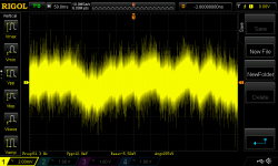
AC-coupled trace of one of the DC-DC outputs loaded with the two opamps. Scope is powered via a 230V/230V isolation transformer to avoid any ground loops.
50Hz at mV levels, no other frequency dominant all the way to 100MHz (my Rigol limit). The noise is measured as 100MHz.
The second voltage has the same trace. The DC/DC converter looks surprisingly clean, IMO.
50Hz at mV levels, no other frequency dominant all the way to 100MHz (my Rigol limit). The noise is measured as 100MHz.
The second voltage has the same trace. The DC/DC converter looks surprisingly clean, IMO.
Attachments
Since the OPA1656 THD was undetectable compared to a voltage divider at <-133dB in my measurement adapter with regular non-inverting voltage follower
Pavel do you have any measurements with the OPA1656 in non-inverting mode you can share?
Jan
Sure, compare screenshot 1 (calibrated loopback) and 2 (DUT OPA1656) in https://www.diyaudio.com/forums/equ...nsation-measurement-setup-36.html#post6140955 . Its distortion is below my compensated soundcard detection capabilities, unlike that for all the other tested opamps.
Thank you all for the words of support. The project is taking much longer than initially intended but I still hope it was not wasted time...
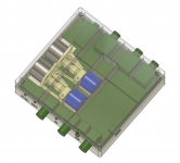
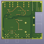
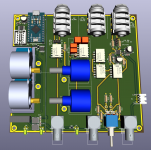
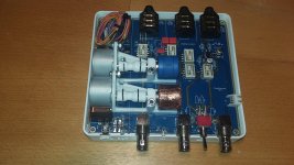
Adapter Mk2 with two calibration potentiometers, OPA1656 output buffer, powered from USB 5V by +/-12V isolated DC/DC convertor. Gerbers off to JLCPCB tomorrow.
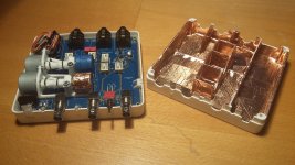
Each calibration path (low-pass filters 1&2, voltage divider 1, voltage divider 2) is enclosed in a shielded compartment made in the top cover. This time I want to try the conductive paint instead of the copper tape.
Each calibration path (low-pass filters 1&2, voltage divider 1, voltage divider 2) is enclosed in a shielded compartment made in the top cover. This time I want to try the conductive paint instead of the copper tape.
Attachments
There are a hold lot of these type of products that work well and are pretty cheap: BMI-S-102 Laird Technologies EMI | RF/IF and RFID | DigiKey No opportunity to 3D print but being solid metal they will work.
Demian, thank you for the link.
The fact is I would like to stay with plastic parts as I can design every detail in CAD. For now I am 3D printing, but for small batches I am looking at options for SLA-printed mold and injection molding. The SLA-printed molds can cut low-batch injection molding price drastically.
Nickel-based conducting paint for plastic PHC05 (IMO the type E-MU use in their USB soundcard enclusures since it is gray too) costs 50USD/kg + shipping from China e.g. China PHC05 Universal Nickel Shielding Conductive Paint Electromagnetic Shielding Anti-static paints | supplier & manufacturer | Shenzhen PH functional materials Co., Ltd.
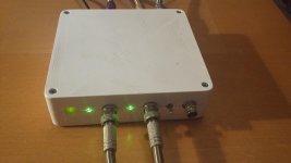
CleanSine v2.0 has two steppers/pots to avoid re-tuning the voltage divider between split-sides calibration of DAC (tuned to LPF level) and ADC-side calibration (tuned to DUT output level).
An illuminated pushbutton allows fast calibration - short press runs ADC-side calibration, long press rstarts split-sides calibration of the DAC. The pushbutton LED - solid green light = connected to the software, slow blinking - ADC calibration running, fast blinking - DAC calibration running. Solid red light = no single or dual tone fundamental detected on any side.
Green LEDs show status of OUT and IN - solid light = enabled, blinking = enabled and distortion-compensating that side.
Still the copper shield, the conducting paint has not arrived yet.
Attachments
Last edited:
The two pots must be minimum-distorting. They are easy to measure - switching to a soldered resistor divider as DUT (basically zero distortion) must not raise the pot-calibrated distortions. Not all pots made the test, only 50% success so far. One had slightly elevated H2, the other was plain bad. I will see what the stats will do with the next batch waiting in transport.
These are DAC-side distortions calculated from combined distortions and LPF transfers measured with pot 1 and pot 2 (those with same distortion as the soldered divider, used in the adapter).
These are DAC-side distortions calculated from combined distortions and LPF transfers measured with pot 1 and pot 2 (those with same distortion as the soldered divider, used in the adapter).
Attachments
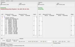
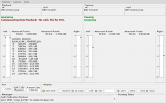
Remeasured opamps, comparison with previous adapter version (the same pot was used for ADC-side calibration). This time the opamp adapter was powered from a linear +/-12V transformer PSU, connected to mains via an isolation transformer (primary/secondary shielded) to lower the capacitive coupling. The +/- supply voltage was 11.7V (last time the SLA batteries fetched 12.7V). The order sorted by THD has not changed, the distortion profiles are very similar to previous measurements https://www.diyaudio.com/forums/equ...nsation-measurement-setup-36.html#post6140955
1) Direct VD - calibration
2) OP1656
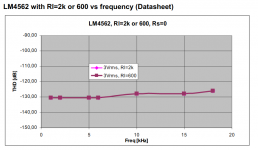
3) LM4562 piece 1
4) LM4562 piece 2
5) NE5532
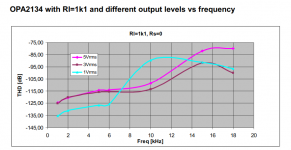
6) OPA2134 piece 1
7) OPA2134 piece 2
1) Direct VD - calibration
2) OP1656
3) LM4562 piece 1
4) LM4562 piece 2
5) NE5532
6) OPA2134 piece 1
7) OPA2134 piece 2
Attachments

Last edited:
- Home
- Design & Build
- Equipment & Tools
- Digital Distortion Compensation for Measurement Setup