Here is the story again from the beginning.
Two fellows make a NOS DAC, non oversampling dac they see the image of 20khz the 24khz because sampled at 44.1khz

They parallel two DACs and manipulate the time addition to "double bit" and the 24khz image vanishes.

What did they do?
If you sample a 20khz with 50khz, than you must generate an image of 30khz, then by adding zero's you oversample and according to legend, the image 30khz should vanish to much higher frequencies.
Two fellows make a NOS DAC, non oversampling dac they see the image of 20khz the 24khz because sampled at 44.1khz
They parallel two DACs and manipulate the time addition to "double bit" and the 24khz image vanishes.
What did they do?
If you sample a 20khz with 50khz, than you must generate an image of 30khz, then by adding zero's you oversample and according to legend, the image 30khz should vanish to much higher frequencies.
I don’t know if I understand your question but I’ll try.
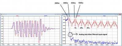
Sampling 20Khz with 50Khz gives an image at 30Khz and at 70 Khz etc. etc.
That’s clearly visible in all the images I gave.
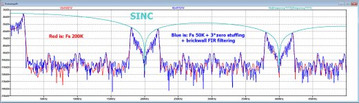
After stuffing zero’s, the 30Khz and the other mirrors are still there in the third image, BUT after the brickwall Fir in the fourth inage the 30Khz is gone. In fact everything between 20Khz and 180KHz is vanished, leaving room for a very easy analogue filter over a 3 decade transition band.
I will do the two sample time shifted version tomorrow and see what result I get. I find it hard to understand why the 24Khz mirror should be removed.
But at least you will have to face a severe Sinc^2 envelope with the first zero at 44.1Khz, whereas the sinc envelope in the 3 zero stuffing and fir filtering situation can be neglected with its first zero at 176,4Khz.
Hans
Sampling 20Khz with 50Khz gives an image at 30Khz and at 70 Khz etc. etc.
That’s clearly visible in all the images I gave.
After stuffing zero’s, the 30Khz and the other mirrors are still there in the third image, BUT after the brickwall Fir in the fourth inage the 30Khz is gone. In fact everything between 20Khz and 180KHz is vanished, leaving room for a very easy analogue filter over a 3 decade transition band.
I will do the two sample time shifted version tomorrow and see what result I get. I find it hard to understand why the 24Khz mirror should be removed.
But at least you will have to face a severe Sinc^2 envelope with the first zero at 44.1Khz, whereas the sinc envelope in the 3 zero stuffing and fir filtering situation can be neglected with its first zero at 176,4Khz.
Hans
The graph in post #270 shows oversampling Vs NOS at 44.1kHz. Progressively increasing the sampling rate wouldn't make them look more and more the same?
Can you please be more explicit, I don’t get the question.
Hans
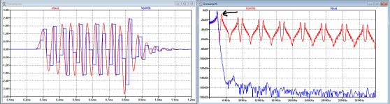
This what your FFT measures the 30khz image, where is it?

This what I measure the 20khz +30khz image.

This what you show after adding zero's.

This what I measure the 20khz +30khz image.
This what you show after adding zero's.
Last edited:
Can you please be more explicit, I don’t get the question.
Hans
It's OK! I just need to grasp your post #282. Thanks!

So, after adding zero's it is still there. Hans also proved that oversampling doesn't chase away the image to have filtered more easily.
The question of post 258 still remains unanswered. What is the probability it is a hoax?
Last edited:
Sorry, obviously I haven't been clear in my explanation what I showed.
That's why I do it again, this time with text in the images.
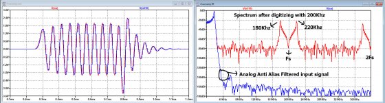
No you can clearly see the 30Khz after sampling with 50Khz in the first image and in the second image with Fs =200k there is no 30Khz
In the third image I have now also plotted both the spectra of the result after [Fs = 200Khz] and [Fs =50Khz + 3 zero stuffing + Fir Brickwall filtering].
I also added the Sinc to show that the original Fs =50Khz now also exactly follows the sinc with it's first zero at 200Khz and no longer one with a zero at 50Khz.
With a perfect Fir fiter, both are indistinguishable.
No correction is needed at 20Khz, since only being 0.18dB, below hearing threshold.
Hans
That's why I do it again, this time with text in the images.
No you can clearly see the 30Khz after sampling with 50Khz in the first image and in the second image with Fs =200k there is no 30Khz
In the third image I have now also plotted both the spectra of the result after [Fs = 200Khz] and [Fs =50Khz + 3 zero stuffing + Fir Brickwall filtering].
I also added the Sinc to show that the original Fs =50Khz now also exactly follows the sinc with it's first zero at 200Khz and no longer one with a zero at 50Khz.
With a perfect Fir fiter, both are indistinguishable.
No correction is needed at 20Khz, since only being 0.18dB, below hearing threshold.
Hans
Attachments
Hayk,
Are you kidding or are you serious, how can you think of a HOAX ?
Everybody can see that the whole spectrum with mirrors between 20Khz and 180Khz from the original 50Khz data has been removed including your 30Khz.
Or are you talking about the mirrors around 200Khz and multiples that haven't been removed.
Why should they, it's a perfect consequence of sampling.
But what I have shown is that you can transform a 44.1K into a 176.4K signal by zero stuffing and Brick wall filtering.
To remove the remains at 200Khz a very simple will do.
Hans
The FIR filter after zeros added , cuts above what frequency?
My 512 point Fir filter was a low pass filter with a transition band from 20Khz to 22.05Khz.
Hans
I also did the test with the two time shifted sample streams, because I had my doubts about the removed first mirror at 24.1Khz, and indeed, it's not the case.
See image below of two added samples time shifted 10usec sampled at 50Khz.
The 30Khz first image is still there, alive and kicking.
If you prefer, I could repeat this with 44.1k instead of 50K.
Hans
.
See image below of two added samples time shifted 10usec sampled at 50Khz.
The 30Khz first image is still there, alive and kicking.
If you prefer, I could repeat this with 44.1k instead of 50K.
Hans
.
Attachments
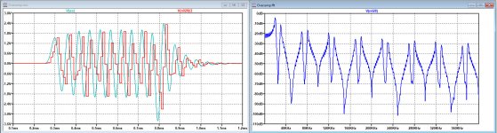
I tried to fit a Sinc envelope around the two time shifted signals.
On one hand the original one at Fs 50Khz should still be there and at the same time since the sample width has halved, a Sinc with it's first zero at 100Khz was expected.
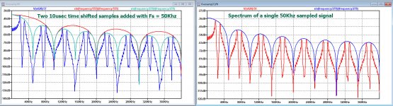
Well, it seems to be a bit of both, as becomes clear in the image below for the two 10usec time shifted and added samples.
The Sinc with it's first zero at 50kHz touches the spectrum at 20K, 80K, 120K, 180K etc, while the Sinc with it's first zero at 100Khz, touches at 30k, 70K, 130K, 170K etc.
A very complex envelope !
The right image is for exactly the same sample but now on it's own without a second time shifted sample.
In this case the Sinc with its first zero at 50Khz fits perfectly.
Hans
On one hand the original one at Fs 50Khz should still be there and at the same time since the sample width has halved, a Sinc with it's first zero at 100Khz was expected.
Well, it seems to be a bit of both, as becomes clear in the image below for the two 10usec time shifted and added samples.
The Sinc with it's first zero at 50kHz touches the spectrum at 20K, 80K, 120K, 180K etc, while the Sinc with it's first zero at 100Khz, touches at 30k, 70K, 130K, 170K etc.
A very complex envelope !
The right image is for exactly the same sample but now on it's own without a second time shifted sample.
In this case the Sinc with its first zero at 50Khz fits perfectly.
Hans
Attachments
Last edited:
I am referring to post 258 non oversampling dac to be a hoax that they could by two DACs shift the 24khz image to much higher frequencies. Your way is always by filtering the image 30khz by a brick wall and not by shifting.
I am looking a way to interpolate digitally the midpoint between two samples by sinc/Hamming window. for 20khz, I have 10 cycles for 1 beat 2khz, as each cycle is 3 samples, I need 30 samples to interpolate the midpoints. It will output a true 2xoversampled. Explained here http://www.audiomisc.co.uk/ArchiveMagazine/33/Upsampling.pdf
As sinc function is symmetrical, I need 15 constants representing sinx/x * Hamming variable to apply on each sample and sum to obtain the value of the midpoint. Maybe such interpolator does already exist.
As sinc function is symmetrical, I need 15 constants representing sinx/x * Hamming variable to apply on each sample and sum to obtain the value of the midpoint. Maybe such interpolator does already exist.
Last edited:
I am referring to post 258 non oversampling dac to be a hoax that they could by two DACs shift the 24khz image to much higher frequencies.
Yes, I agree. For shifting a frequency you will need a multiplier and not an adder.
Hans
I’ll have to read the article, but sinc convolution in the time domain is the same as brick wall in the frequency domain.
In fact what I saw in a quick glimpse is exacly like the Fir filter that I used.
But I increased Fs a factor 4.
Hans
In fact what I saw in a quick glimpse is exacly like the Fir filter that I used.
But I increased Fs a factor 4.
Hans
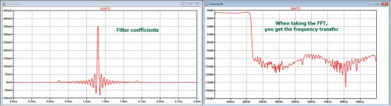
Here are at the left the filter coefficients of my FIR, and when taking it's FFT , you get the FR.
Hans
P.S. I used two in series to get twice the damping.
Not the best way, but good enough for the test.
Hans
P.S. I used two in series to get twice the damping.
Not the best way, but good enough for the test.
Attachments
Last edited:
I am looking a way to interpolate digitally the midpoint between two samples by sinc/Hamming window. for 20khz, I have 10 cycles for 1 beat 2khz, as each cycle is 3 samples, I need 30 samples to interpolate the midpoints. It will output a true 2xoversampled. Explained here http://www.audiomisc.co.uk/ArchiveMagazine/33/Upsampling.pdf
As sinc function is symmetrical, I need 15 constants representing sinx/x * Hamming variable to apply on each sample and sum to obtain the value of the midpoint. Maybe such interpolator does already exist.
Isn't that a standard two times interpolating filter, that is, a combination of inserting zeros and brick-wall low-pass filtering? Instead of a windowed sinc, you can also use the Parks-McClellan program (based on the Remez exchange algorithm) to find a finite impulse response that approximates the ideal sinc.
Yes, Marcel you ate right.
The guy inserted one zero after each sample instead of the three that I did.
For some strange reason he did not mention this zero stuffing.
So indeed, it is exactly what I did in the previous simulations.
How to find the coefficients for your FIR filter is up to the designer, but it has to be long enough and the calculation has to be accurate.
What I mentioned earlier is that you will need a fast DSP to do the math.
Hans
- Home
- Source & Line
- Digital Line Level
- Analog Delta-Sigma interpolation DAC