Nice work measuring a real one, what are you using to measure with it is very noisy.
its just a calibrated dayton mic. I didn't really do it long or loud enough (in a unit). its just 256k length. and normalizing them obviously magnifies it. didn't feel there was much point getting really nice measurements.
Of course it’s a pick your poison situation. The only practical solution for narrow vertical pattern control down low is a MEH, but that’s a whole different story. Going for narrower vertical pattern in a woofer plus asymmetrical waveguide situation always means you only get pattern control in the vertical only much higher than in the horizontal and the transition will (best case) not be as smooth. Wayne Parham’s measurements show his choice of compromises quite clearly and unlike almost anybody else he shows vertical measurements fully aware it’s always a compromise.
But if one could come up with a waveguide that gains its pattern control really smoothly (as I think Mabat is aiming for as well), coupled with a powerful driver like the HF1440 it could be crossed below where it has pattern control and the woofer is not beaming yet. Then there won’t be any pattern flip since all the gaining of the pattern is done by the waveguide. The question is then ‘just’ how low do you want vertical pattern control vs how much of it, no?
(Ignoring the accompanying lobing behaviour, which also depends on the crossover and people have very different opinions on this anyway)
Sorry, don't know what happened!
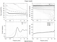
What is going on starting at 9kHz?
pretty much exactly what is happening in the sim (see mabats post on what i did wrong for the real sim)
it shows that you can pretty much trust the results you're getting in the sim if you model a hard dome.
I think its probably also worth trying a silk dome as they seem to be a bit more forgiving. but its impossible to model them as far as I know.
It is the horn that sets the pattern so making it multiple entry doesn't in any way lower the control frequency, you still get flip if you make it too asymmetric. Multiple entry allows it to appear as a single source to a lower frequency which is not the same thing.The only practical solution for narrow vertical pattern control down low is a MEH, but that’s a whole different story.
This is the trade off, what's more important to you smooth pattern control or reflection control.The question is then ‘just’ how low do you want vertical pattern control vs how much of it, no?
The question I'm still missing answered is what's better: a spectrally flat vertical reflection or a stronger vertical reflection that is spectrally low-passsed? Because these two cases really represent the "trade-off" (which I don't see as trade-off at all after all - to me losing pattern control is always worse).
Vathek have you tried with Ath4? I've noticed trying to simulate axisymmetric waveguides the depth parameter is paramount to get smooth results and "optimal" value depends on the coverage pattern. Also, the profile is affected by both and other parameters. These observations let me realize that optimizing different coverage patterns on same 3D device would require another dimension or something 😀 So, not possible to have "perfect" horizontal and vertical response unless it is an axisymmetric device. Of course it is just a compromise and maybe worth it to build both, evaluate both and then determine which one is better set of compromises for your listening space.
On the other hand you could make a narrow axisymmetric one that has really smooth DI so possibly large enough horizontal sweetspot without shooting to the ceiling too much. You can actually calculate from your listening distance how narrow you would like your vertical polar pattern to be for meaningful difference comparing to your current system. Might be anything from 10-120 degree vertical coverage that is enough and still have perfect axisymmetric waveguide and wide enough sweetspot. Example 3m listening distance, 1m tweeter and listening height, 2,5m room height the spot that hits ear through ceiling is about 45 degrees so with 90 degree vertical dispersion ceiling bounce is at least 6db less than the direct sound. If it was 60 degree vertical dispersion the level via 45 degree reflection could be something like 10db less than direct sound. Few decibels is sometimes a lot, sometimes not.
Yeah I think you could actually get away with quite narrow dispersion horizontally with low diffraction and smooth DI device like the Ath4 can help to create. And still have nice sound on quite large area. Less first reflections as well. Depends on your room acoustics and how you can position the speakers and the listening spot so building few different waveguide would be a great way to find out what works better.
Last edited:
It is the horn that sets the pattern so making it multiple entry doesn't in any way lower the control frequency, you still get flip if you make it too asymmetric. Multiple entry allows it to appear as a single source to a lower frequency which is not the same thing.
You're right, I somewhat conflated two things. Also MEH are generally deeper, which helps with holding a narrower vertical pattern. But it really is a separate issue and not a unique property of a MEH.
This is the trade off, what's more important to you smooth pattern control or reflection control.
The suggestion I was trying to make is that if you take a powerful driver and cross below where the waveguide has any significant pattern control and the woofer does not beam yet, you avoid the vertical narrowing and subsequent widening before the waveguide actually starts controlling the pattern. Only now you truly reduce the trade-off to pattern control vs reflection control. When doing it the standard way and crossing over where the woofer and wg match horizontally, you create an additional problem in the vertical, which makes the trade-off much worse imo. It just requires a powerful driver and a waveguide with a nice transition from no control to full control, which should be possible to design thanks to Ath4.
The question I'm still missing answered is what's better: a spectrally flat vertical reflection or a stronger vertical reflection that is spectrally low-passsed? Because these two cases really represent the "trade-off" (which I don't see as trade-off at all after all - to me losing pattern control is always worse).
I don't feel this question can be answered universally, although I tend to agree that spectrally flat is probably the better answer in most cases. What I was suggesting was merely to actually narrow it down to this choice. I tried to explain again just above.
I have nothing against narrow vertical directivity but people seem to miss how difficult it is to achieve that without losing the pattern control: to get from 90° to 50° you would have to double (at least!) the width and the depth of the waveguide to maintain the same quality. This is no subtle thing.
90x75° is fine, 80x60° is also fine.
Problem is that to cross that low you are either going to reach the limits of most CDs, or you are talking about using a small waveguide, which is pointless unless space constraints dictate it. The reason people cross over the ’standard way’ where the woofer and WG match is usually because that is where the lower limit of the CD is, which has traditionally been around 1000hz ~12” woofer.
Vathek have you tried with Ath4?
I have not. I don't have a Windows computer and for some reason I couldn't get it to work in Parallels and gave up.
I'll have to get another ssd and do a proper dual boot. It's a pretty powerful machine, so it would actually be good for simulations.
Regarding the ceiling reflections. In my case – a studio situation where I can easily just install big absorbers on the ceiling (the floor might be more poblematic) – I can also argue that I don't really care about the vertical reflections as they can easily be taken care of without loosing necessary spatial cues (unlike in the horizontal) and focus on the cleanest possible forward lobe. This would lead to trying to minimize CTC though. But this is probably not beneficial for most domestic situations.
Problem is that to cross that low you are either going to reach the limits of most CDs, or you are talking about using a small waveguide, which is pointless unless space constraints dictate it. The reason people cross over the ’standard way’ where the woofer and WG match is usually because that is where the lower limit of the CD is, which has traditionally been around 1000hz ~12” woofer.
Agreed, that's why I specifically mentioned the HF1440. It takes a really powerful driver to do that and even then it will only work in domestic situations with moderate SPL demands.
MEH is true solution for the CTC requirement, or maybe two woofers side by side instead of one big one has some potential. It is about half wavelength from throat to lip with axisymmetric device if the crossover should happen where the waveguide loses control of the polars so can't get much closer than this no matter what unless the woofer is inside the waveguide and I'm not sure if 1/2 WL distance has too much benefit over a bit more since they still are separate sources of sound.
If the "perfect" axisymmetric waveguide is compromised with something I'd say (before we see simulations of what the midrange taps do) one should go for a MEH to get a point source, the most significant difference achievable by sacrificing some diffraction. I've never heard a MEH or Ath4 script based waveguides so this is just thinking from the visual data presented in the forums 😀
If the "perfect" axisymmetric waveguide is compromised with something I'd say (before we see simulations of what the midrange taps do) one should go for a MEH to get a point source, the most significant difference achievable by sacrificing some diffraction. I've never heard a MEH or Ath4 script based waveguides so this is just thinking from the visual data presented in the forums 😀
Last edited:
Does anyone think there is a practical limit to WG size, assuming something like the freestanding round with rollback in this thread, where it's not worth it to go so large? Say 500mm ~ 500hz XO. (Assuming one has the space)
Last edited:
If I had a single driver capable reaching Schroeder frequency, whatever that would be, I could imagine using waveguide that large (probably not larger than about 1 m though 🙂)
Does anyone think there is a practical limit to WG size, assuming something like the freestanding round with rollback in this thread, where it's not worth it to go so large? Say 500mm ~ 500hz XO. (Assuming one has the space)
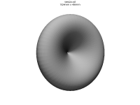
Just for kicks tried 1.5m diameter donut 😀 If I remember correctly this kind of shallow waveguide with huge roundover scaled from 20cm to 1.5m pretty easily. I'm not sure if I had to tune anything else than depth parameter and the graphs looked pretty much the same except the frequency pattern was held went lower. It is not the best one and not the smallest possible, interesting test though.
Attachments
But then if you have such a powerful driver, why not mate it to a larger WG?
Whether it's worth to put that much strain on the driver, I don't know. But the reason behind the idea of deliberately crossing over lower than where the waveguide can hold its pattern was to avoid the narrowing, widening and narrowing again in the vertical, when you use the woofer to transition from omni to a non-axisymmetrical waveguide's pattern and rather use the waveguide to do the transition.
Just for kicks tried 1.5m diameter donut 😀 If I remember correctly this kind of shallow waveguide with huge roundover scaled from 20cm to 1.5m pretty easily. I'm not sure if I had to tune anything else than depth parameter and the graphs looked pretty much the same except the frequency pattern was held went lower. It is not the best one and not the smallest possible, interesting test though.
Ha! A large coax driver will be able to output 300Hz on these and if you lock yourself in your toilet with two of these bad boys, you'll even get to Schroeder.
- Home
- Loudspeakers
- Multi-Way
- Acoustic Horn Design – The Easy Way (Ath4)