Of additional concern is the increased current required to use these lower noise alternatives along with their greater complexity. I'm not able to access your "829" post at the moment as the site bandwidth has been exceeded but am familiar with the others and have used them particularly the GLED.
The greater current required (approx X 5) results in a lower feed resistor value which in turn means less rejection. In addition the dynamic impedance of the LM329 up to about 10kHz is lower at less than an ohm than the GLED which is circa 4 ohms, further reducing the references rejection. I compensated for this by using a cap multiplier in the feed and found this had a much more significant effect than the three fold reduction in noise. I expect this has much to do with the filter to the opamp input. It is at very low frequencies, i.e. below the cutoff of that filter, that the noise benefits of the GLED and other higher current references will be most beneficial. How beneficial must depend on the demands of the regulators load w.r.t. low frequency noise.
I am certain that any of these changes would be very hard to detect in double blind testing let alone determine which was best based on my many hours of swapping between them. Frankly, I'm undecided and I've built dozens of these. It is diminishing returns and there is more to be gained by remote sensing, correct earthing and keeping the regulator as close as possible to the load IMHO.
John

John Luckins; said:Of additional concern is the increased current required to use these lower noise alternatives along with their greater complexity. I'm not able to access your "829" post at the moment as the site bandwidth has been exceeded but am familiar with the others and have used them particularly the GLED.
The greater current required (approx X 5) results in a lower feed resistor value which in turn means less rejection. In addition the dynamic impedance of the LM329 up to about 10kHz is lower at less than an ohm than the GLED which is circa 4 ohms, further reducing the references rejection.
The PM829 is like the use of a Zener with a series diode (such as 1N4148) for temperature compensation but instead of the 1N4148 another Zener is used. So the PM829 consists of two 1N5234B 6.2V Zener diodes. (Is that called inverse series connection?) In the PM829 link it is described as "composed of a reverse-biased zener in series with a forward biased diode". Both being 1N5234B 6.2V Zener diodes in the case of the PM829.
If increased reference current and the dynamic impedance are more important concerns then perhaps I should just use the TL431 that I have? Should I increase C9 (originally 120uF) due to concerns about TL431 noise? Or is that unnecessary?
Is the TL431 the best of my choices (TL431, LED or Zeners)? Or is it a poor choice? (I ask since others have criticized the noise.)
Last edited:
Whether there will be a difference in the outcome will depend on the load. In my opinion the rejection is the most important aspect as low rejection can allow feedback from the load straight into the reference. For this reason I now always use a cap multiplier to filter the voltage from the output before it feeds the reference resistor. I can hear the improvement this makes. I also then use the GLED and drive it at circa 5mA. I avoid zeners as they are noisier than good LED's, even ones with a reversed zener to aid temperature stability. For digital DAC and clock feeds I also increase the filter capacitor to 220uF as I think this beneficially reduces the low freq noise even further. Temperature stability isn't an issue with the GLED when I have used it on ESS and Ti DACs.
I have always started with either a LM329 or a TL431 and then when every DAC feed has its own separate supply and regulator, I have gone back and tried the cap multiplier and GLED, altering the gain accordingly. At that point the only way to tell if it is worthwhile on its particular load is to listen/measure. From listening alone on many occasions (>15) I have found the differences when replacing the TL431/LM329 after adding the cap multiplier to be barely perceptible let alone quantifiable. You may have better equipment than me (ears and test kit) so you may be better able to judge changes and/or improvements. It would be great if you did.
john
What are you using for the capacitance multiplier? Something like a BC550C or 2N5089, 100 to 1000 Ohm resistor and a 100 or 220uF capacitor?
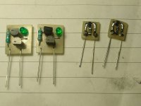
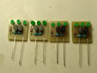
By GLED I assume you mean Walt Jung's GLED431 reference cell, not just a Green LED. https://refsnregs.waltjung.org/GLED431_An%20Ultra%20Low%20Noise%20LED%20Reference%20Cell%20_Walt%27s%20Blog%202014_092418.pdf
By GLED I assume you mean Walt Jung's GLED431 reference cell, not just a Green LED. https://refsnregs.waltjung.org/GLED431_An%20Ultra%20Low%20Noise%20LED%20Reference%20Cell%20_Walt%27s%20Blog%202014_092418.pdf
I remember treading this path some time ago, every combination ended in a compromise one way or another, Jan's combination is best stuck with.
If you go the GLED431 route, the REF voltage will wander with temperature - as mentioned in the article, and is made worse by the gain of the AD825.
The TL431 is noisy, I added a 0.1Hz 24dB Sallen Key filter between the TL431 and the AD825 input, it's a lot more components, but as I said, everything is a compromise.
Of additional concern is the increased current required to use these lower noise alternatives along with their greater complexity. I'm not able to access your "829" post at the moment as the site bandwidth has been exceeded but am familiar with the others and have used them particularly the GLED.
The greater current required (approx X 5) results in a lower feed resistor value which in turn means less rejection. In addition the dynamic impedance of the LM329 up to about 10kHz is lower at less than an ohm than the GLED which is circa 4 ohms, further reducing the references rejection. I compensated for this by using a cap multiplier in the feed and found this had a much more significant effect than the three fold reduction in noise. I expect this has much to do with the filter to the opamp input. It is at very low frequencies, i.e. below the cutoff of that filter, that the noise benefits of the GLED and other higher current references will be most beneficial. How beneficial must depend on the demands of the regulators load w.r.t. low frequency noise.
I am certain that any of these changes would be very hard to detect in double blind testing let alone determine which was best based on my many hours of swapping between them. Frankly, I'm undecided and I've built dozens of these. It is diminishing returns and there is more to be gained by remote sensing, correct earthing and keeping the regulator as close as possible to the load IMHO.
John
Good overview John, fully agree.
Jan
I was wondering if someone could help check these noise calculations.
Now TL431: 120nV/√Hz
The total integrated noise due to TL431 will be 120nV/√Hz * √(2.5) = 190nV RMS.
However we need to scale by 6.9V/2.5V because the LM329 is a 2.5V reference and the TL431 is a 6.9V reference.
So in an equivalent usage the TL431 is like (6.9/2.5)*190nV RMS = 524nV RMS.
But the TL431 is only 2.5V so I could use a larger capacitor with a lower voltage rating. Perhaps change C9 to a 1500uF 6.3V capacitor and R4 to 1000 Ohms. (I have leftover 1500uF 6.3V motherboard replacement capacitors.) Now for the TL431 we have:
Is this a good idea? Using TL431 with 1500uF C9 and 1000 Ohm R4? Am I missing something that needs to be considered?
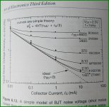
LM329: 70nV/√Hz
For ease of calculations consider R5 = 500Ohms and C9 = 200uF. The output bandwidth will be 1.6 Hz scaled up by PI/2 from the integration from DC to infinity of ArcTangent, or 2.5Hz bandwidth.
The total integrated noise due to LM329 will be 70nV/√Hz * √(2.5) = 111nV RMS.
For ease of calculations consider R5 = 500Ohms and C9 = 200uF. The output bandwidth will be 1.6 Hz scaled up by PI/2 from the integration from DC to infinity of ArcTangent, or 2.5Hz bandwidth.
The total integrated noise due to LM329 will be 70nV/√Hz * √(2.5) = 111nV RMS.
Now TL431: 120nV/√Hz
The total integrated noise due to TL431 will be 120nV/√Hz * √(2.5) = 190nV RMS.
However we need to scale by 6.9V/2.5V because the LM329 is a 2.5V reference and the TL431 is a 6.9V reference.
So in an equivalent usage the TL431 is like (6.9/2.5)*190nV RMS = 524nV RMS.
The output bandwidth will be 0.11 Hz scaled up by PI/2 from the integration from DC to infinity of ArcTangent, or 0.167Hz bandwidth.
The total integrated noise due to TL431 will be 120nV/√Hz * √(0.167) = 49nV RMS.
However we need to scale by 6.9V/2.5V because the LM329 is a 2.5V reference and the TL431 is a 6.9V reference.
So in an equivalent usage the TL431 is like (6.9/2.5)*49nV RMS = 135nV RMS.
So if 1000 Ohms is reasonable for R4, is this perhaps a reasonable compromise for using a TL431 in place of the LM329?
I would appreciate it if someone could check my calculations. If something is wrong I would appreciate it if you could explain the error and how to correct it.The total integrated noise due to TL431 will be 120nV/√Hz * √(0.167) = 49nV RMS.
However we need to scale by 6.9V/2.5V because the LM329 is a 2.5V reference and the TL431 is a 6.9V reference.
So in an equivalent usage the TL431 is like (6.9/2.5)*49nV RMS = 135nV RMS.
So if 1000 Ohms is reasonable for R4, is this perhaps a reasonable compromise for using a TL431 in place of the LM329?
Is this a good idea? Using TL431 with 1500uF C9 and 1000 Ohm R4? Am I missing something that needs to be considered?
Last edited:
Possibly a typo but you say the LM329 is a 2.5v ref and the TL431 is a 6.0v. In fact it is the other way round, but i think you scale up the noise of the TL431 to the equivalent of 6.9v correctly.
I don't know how to calculate it but the leakage current of a low voltage 1500uF electrolytic will create its own noise. Sort of need to know where that exceeds the noise contribution of the reference methinks.
Better in my view to get the root cause of the noise down from the off by using the GLED if you are going to be purist about it.
By the way, when I said I use a cap multiplier to feed the reference chain i also use the same cap multiplier to feed the opamp and its decoupling capacitor.
The reason for using circa 500 ohms for both the opamp inputs is a noise issue as well. Below this value the opamp noise dominates.
John
P.S. I think there is also a 2.5 volt version of the LM329 as well which may be worth a look at. Somewhere here if you search for it there are some LED and zener noise measurements at different currents which are helpful.
Last edited:
Yes, that was a typo.
Which transistor and which component values (R, C) do you use for the capacitance multiplier?
Which transistor and which component values (R, C) do you use for the capacitance multiplier?
I assume 5 mA for the opamp feed and 5mA for the reference. I use a BC550C for positive regulators with an Hfe at 10ma of approx 400. I normally use a 36k ohm and a 10uF ceramic or MKS Wima and add a small (120 ohm) base stopper resistor to ensure no oscillation. Total drop is therefore 1.6 volts.
It is fine to drop 1.6 volts for >5 volt output regulators but for 5 volt ones I feed the cap multiplier from the tracking pre regulator, either an LM317 or a LT3045.
There is an alternative to the cap multiplier that I have used on 5 volt regs to allow me to continue feeding the reference from the output while increasing rejection and isolation of the reference. This is a simple pnp/green LED based constant current source set for 5mA (a 220 ohm resistor). Using a high early voltage PNP here like a ZTX 753 gives a very good current source with only a 1.8 volt drop out voltage. That is fine with a 2.5 volt reference i.e. an LM329-2.5 or a GLED.
Hope that makes sense...
J
I think I follow that.
I don't have ZTX753 but I think 2N5551/2N5401 have pretty high early voltage. I wonder about some others that I have (C2383, D669A & C2705) however it seems a little difficult to find published early voltage numbers. (I just found Mark Johnson's early voltage measurements over here #22.)
I was planning to try the super regulator first for the I/V stage of my ES9038Q2M.
Then I was thinking about maybe trying it for VCCA. And maybe AVCC_R/L. For 3.3V I was thinking of either using an LM317 to regulate the supply for the op-amps and reference. Or I was thinking of using the I/V super regulator +/-18V outputs as the supplies for the op-amps in the 3.3V super regulators.
Other have recommended using op-amp buffers after references for ES9038 AVCC_R/L or using the LM317 Denoiser or the LM317 based Nazar shunt regulator.
Last edited:
I have used the 2N5551's in the past. They may even be slightly better than the ZTX753 as they have a greater Hfe and a similar Early voltage and low quasi-saturation. I run the LED's at around 2mA and split the resistor to 0v into two equal halves. I then run an electrolytic from their junction to the incoming rail, 47uF-100uF to smooth out the LED current even more.
I'm using super-regs this way on all the supplies to my Soncoz SGD1. The I/V first stage opamps are OPA1612's and they work best at +/- 12 volts. The refs of the pair of ESS9038Q2M analogue feeds are from the ESS 9311 regulator but even the feed to these benefits from a well sorted super-reg. Other on board regs are fed by 5v super-regs. I'm currently working on designing my own regs using surface mount components where possible to get the size down so they can be mounted directly at the load. I'm still relying on remote sensing and quite long distances.
I would suggest completely separate feeds including transformers for each load is ideal. The largest improvement is the final one as all feeds become totally independent. The ES9311 is a rather useful device as well. It feeds the 3.3v references of the DAC's.
Oh and I precede each modified super-reg with a cap multiplier and choke regulation. 5 enhanced super-regs. A bit of a monster!
John
What about combining this CCS with the GLED431?
It uses a couple extra transistors and 1N4148 diodes but I have lots of those. Plus it sounds like a fun combination of building blocks to try together.
- CCS #72 (Split R2 and bypass.)
- GLED431 https://refsnregs.waltjung.org/GLED431_An%20Ultra%20Low%20Noise%20LED%20Reference%20Cell%20_Walt%27s%20Blog%202014_092418.pdf
It uses a couple extra transistors and 1N4148 diodes but I have lots of those. Plus it sounds like a fun combination of building blocks to try together.
Last edited:
Yes, yes and yes, as long as you have the voltage headroom, and you do for your I/V stage regs. I have one reg where I used a cascode but with red LED's rather than IN4148's. My I/V regs still use the LM329's. Might change them to a cascoded CCS GLED next. BTW it is better for noise to put additional LED's in series in the GLED to get a higher voltage reference than to increase the gain of the opamp.
J
J
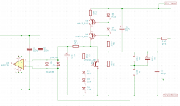
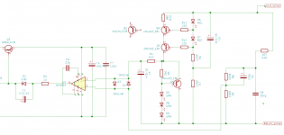
How does this schematic look? Does it look like this will work?
Is the fairly low noise 2N4403 better than the 2N5401 for the GLED431? (I don't have ZTX951.)
Is the fairly low noise 2N4403 better than the 2N5401 for the GLED431? (I don't have ZTX951.)
Attachments
Last edited:
That's a yes to the 2N4403. BC560 would be OK as well if you have them.
What you have will work but may I humbly suggest some tweeks?
Suggest changing R6 and R7 to 2k2 to reduce current through LED's to approx 2mA. This reduces the Fco of C5 and R7 a little.
Suggest base stopper resistors for both Q3 and Q4 for guaranteed stability, 100-220R should do it.
Of the 5mA going through the GLED6v I would get more passing through the emitter of Q5 by doubling R5 to 300R. That trebles the current in the emitter to 3mA and reduces the effective impedance of the reference from 26 ohms to about 9 ohms. Even more rejection, likely imperceptible increase in noise from the LED's.
I don't normally use the R15/C8 combo but these can be omitted or linked out on any prototype board. I also prefer not to use C6 at all as it can introduce stability issues depending on the load capacitance/ESR and the opamp used (5534 not stable below a gain of 3!) and only gives a small decrease in noise. Also OPA1611 is loads better than the 5534 and doesn't need a compensation capacitor. May still be pin compatible if you use a socket here and external compensation on the 5534.
You may want to check out the ALWSR documentation over on the Pink Fish forum for layout, remote sense and tracking pre reg options.
Otherwise you are hot to trot!
John
Ok. I have updated the schematic. Should I include the capacitance multiplier? Or is that unnecessary now that I have the CCS? (I assumed it was now unnecessary which is why I have not added it yet.)
For op amps I might switch to NE5532 and that way I can plug in LM4562NA (which is the best op-amp that I currently have). Not sure yet. I also have a couple OPA228 but those are not really for unity gain either.
Still trying to decide between A1015 and 2N4403 for the upper transistor in the CCS. 2N4403 likely lower noise but A1015 likely higher gain. Maybe no real difference here.
Attachments
How does this schematic look? Does it look like this will work?
Is the fairly low noise 2N4403 better than the 2N5401 for the GLED431? (I don't have ZTX951.)
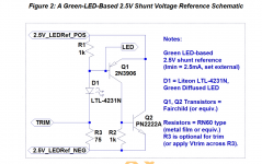
Walt Jung says this in that same article;
Note that the forward voltage of the LTL-4231N green LED (LiteOn) and the Vbe of the ZTX951 (Diodes Inc.) conveniently add, producing the desired Vout of 2.5V.
These two parts should not be changed if you expect to get close to 2.500V
but it also has a solution for that, it has a couple of nV higher noise than GLED431 but it uses 2N2222 and 2N3907 instead of ZTX951
https://refsnregs.waltjung.org/2New_Vrefs_082715_Draft.pdf
I use the same reference in Walt Jung shunt regulators that power digital circuits in my DAC and with three LEDs + 1N4148 for 6.8V instead of LM329 in WJ Improved_PN_Regs, but with 4A output current for JLH69 and Hiraga Le Monstre amplifier.
I supply the reference directly from the output voltage but via CCS with 2SK246 instead of a resistor, the minimum current in this case is 2.5mA while for GLED431 it is 3,5mA.
In all cases when I installed the WJ LED reference, the difference in sound was immediately felt, regardless of whether I changed the LM329 or LM4040 and ADR525, which I used as a 2.5V ref.
The table shows what makes the ZTX851 (951) the best option in the GLED431.
Attachments
Last edited:
I'd really recommend the cap multiplier for the opamp anyway and you might as well at least allow for a link from its output to the Vref feed as well. There's not much in it between the 2N4403 and the 2SA1015 but the 2SA1015 appears to have slightly higher gain yet higher capacitances. On balance I'd go for the higher gain of the 2SA1015 as the capacitances aren't significant within a cascode.
John
John
Walt Jung says this in that same article;
Note that the forward voltage of the LTL-4231N green LED (LiteOn) and the Vbe of the ZTX951 (Diodes Inc.) conveniently add, producing the desired Vout of 2.5V.
These two parts should not be changed if you expect to get close to 2.500V
but it also has a solution for that, it has a couple of nV higher noise than GLED431 but it uses 2N2222 and 2N3907 instead of ZTX951
https://refsnregs.waltjung.org/2New_Vrefs_082715_Draft.pdf
I use the same reference in Walt Jung shunt regulators that power digital circuits in my DAC and with three LEDs + 1N4148 for 6.8V instead of LM329 in WJ Improved_PN_Regs, but with 4A output current for JLH69 and Hiraga Le Monstre amplifier.
I supply the reference directly from the output voltage but via CCS with 2SK246 instead of a resistor, the minimum current in this case is 2.5mA while for GLED431 it is 3,5mA.
In all cases when I installed the WJ LED reference, the difference in sound was immediately felt, regardless of whether I changed the LM329 or LM4040 and ADR525, which I used as a 2.5V ref.
The table shows what makes the ZTX851 (951) the best option in the GLED431.
I really like your two pin ref mock ups, very similar paths to mine. Would recommend you try the OPA1611 in place of the AD825 and try the cap multiplier on at least the opamp. I would be surprised if you didn't hear the difference. Also have you tried splitting your R3 and linking the join to the supply with say a 100uF cap??
john
- Home
- The diyAudio Store
- Super Regulator