hopefully i'm not annoying with this but after looking up Plane Wave Tube measurements i'm still a little befuddled with it's complexity and hope that i can ask a few questions if i may?
Now I noticed you made the same mistake as almost everyone else - when simulating a dome tweeter, you have to set the axial velocity of the driving elements (the default is radial):
Source.Velocity = 2
...
Happens to the best of us! 😀
If one puts a Tritonia flush into a box, and the front baffle adds a one inch round over on all four edges, and not much else (WG comes right up to the edge), then that box is air gapped above the box for the woofer, which has the same round over, would one see a performance improvement anything like the freestanding OS-SE?
That we will never know but I doubt it. The improvement is not in making a gap but in as gradual curvature change as possible, which is exactly what a proper rollback is doing (up to a point where it doesn't really matter anymore). Tritonia hasn't been measured or simulated anywhere else than in an infinite baffle yet. The existing roundover is not nearly as smooth as for the latest round waveguides but this one is not round so the effect is still to be evaluated.
Last edited:
It will come to life as soon as this pandemic madness ceases, which I still hope will happen some day.
I'm soo looking forward to everything in this sentence! 🙂
It ceases when you (and everyone else) start ignoring it


OK, when it comes to opinions, impressions and ideas, I can tell you what I think would work best: a large free standing round OS-SE waveguide with 1.4" driver such as the HF1440, crossed over to a cardioid-like open baffle woofer around 500 - 600 Hz
How large? or put differently, how small could that be? I ask because you've indicated elsewhere that the freestanding OS-SE doesn't need to be as large as the classic "match the diameter to the wavelength"
Well obviously the directivity control is still limited by the size of the mouth but that doesn't prevent from using the driver even lower with these waveguides, which are exceptionally smooth all the way down. I believe it could be 0.5 - 0.6 m across without a problem.
What would you like to know?hopefully i'm not annoying with this but after looking up Plane Wave Tube measurements i'm still a little befuddled with it's complexity and hope that i can ask a few questions if i may?
Was Tritonia script/stl ever released? I'd like to print and test it if it's available...
Last edited:
Are there any budget options for going low that are less than the HF1440? Even if it sacrifices top end, which I don't rank as important as others.
Last edited:
Well obviously the directivity control is still limited by the size of the mouth but that doesn't prevent from using the driver even lower with these waveguides, which are exceptionally smooth all the way down.
Is the idea here to let the waveguide do (or be part of) the transition into a controlled pattern rather than letting a large woofer beam and then cross over above that?
If one puts a Tritonia flush into a box, and the front baffle adds a one inch round over on all four edges, and not much else (WG comes right up to the edge), then that box is air gapped above the box for the woofer, which has the same round over, would one see a performance improvement anything like the freestanding OS-SE?
I made a comparison of a waveguide designed to terminate in a flat baffle and roundover with the same guide made to look like a freestading guide with a 50mm roundover.
2 way waveguide speaker build ABEC modelling
2 way waveguide speaker build ABEC modelling
If you look past the mesh issues that make the freestanding one look messy not much changed with the overall directivity. So you can make a pretty decent waveguide that terminates flat. I know this doesn't answer completely answer your question but maybe together with mabat's answer above it helps.
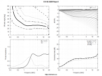
Basically, yes, that's one aspect. The second is that it really seems to me that the free standing waveguides reach somewhat lower with the controlled directivity than when in a box. For example this is the "sand horn", ⌀336 mm (~13.2") across. I don't have a simulation for a similar WG in a box but I would say it's pretty good result for the size.Is the idea here to let the waveguide do (or be part of) the transition into a controlled pattern rather than letting a large woofer beam and then cross over above that?
Attachments
If you look past the mesh issues that make the freestanding one look messy not much changed with the overall directivity. So you can make a pretty decent waveguide that terminates flat. I know this doesn't answer completely answer your question but maybe together with mabat's answer above it helps.
That is informative.
Presumably the 336mm is the total dimension 'after' the roundover? That would equal something like maybe a 270mm waveguide in a baffle with large roundovers. Looking at it that way, it's actually tiny for 1000Hz pattern control.
Even if I interpret fluid correctly that large baffle roundovers have a similar effect as freestanding wg with rollback, it still seems to get more pattern control out of its small size.
Even if I interpret fluid correctly that large baffle roundovers have a similar effect as freestanding wg with rollback, it still seems to get more pattern control out of its small size.
What people still seem to miss somehow is that this is actually far from being equal. In a baffle you can have the same roundover only at a limited number of points (typically only three), the rest of the circumference just continues with a segment of flat surface, which is not as smooth continuation of the profile... For me that's the reason why a round waveguide is really not the best choice for a flat (rectangular) baffle.... That would equal something like maybe a 270mm waveguide in a baffle with large roundovers.
Last edited:
Hmm, how is that, that this velocity is independent of a throat impedance? Doesn't the throat impedance affect excursion, etc.? I was under the impression that it does 😕
It's not independent of the load. But remember that the load on the driver above "cutoff" is exactly the same as the plane wave tube. Below cutoff there will be some issues, but they are small(ish) and not of much co0ncern in this region. Because the load falls the excursion will increase slightly (knowing that the acoustic load is a small fraction of the EM load,) but this occurs only in a region where the output is falling.
I would be interested especially in the region where the output is falling, typically below 2 kHz or so. I guess I should try that out to see what I get...
For me that's the reason why a round waveguide is really not the best choice for a flat (rectangular) baffle.
By "round" you mean "constant radius"? Because all "roundovers" are "round".
- Home
- Loudspeakers
- Multi-Way
- Acoustic Horn Design – The Easy Way (Ath4)