I definitely do not have the knowledge to design a card. But I would certainly like to participate in a Group Purchase if some knowledgeable person designs the card.
Thank you Maringo, I have ordered the single output pair boards from Ali express and will update here once I receive them.
@drmaftoon:
I recommend you to get asap the documents about the WHA-217, there are some more interesting pictures than I posted. So, if you send me a PM with your eMail, I will send you the whole set via Wetransfer.
@Hattori:
Sorry, I will not design a PCB, I have to design some for me, for another project, but this is a job that I always refuse to do, it takes long time and patience and I'd end up arguing with my wife.

I think more people would be interested if someone would design a PC Boards.
Several outstanding and fast designers we have at the forum, but I only can speak what I would love to do.
Also, I have some other projects on hold in my hand (need to be tested and finalized).
I planed to build these amp with 3 pairs, I do have the stuffed PC boards but seeing the progress of the fellow DIY-ers I decided better to focus on another project instead of finishing these.
Someone did run several simulations for the best performance but also I was watching his progress and since to me he abandoned or suspended these projects also after several real-life testing.
I do have some (personal) problems also from the last couple of years, starting a new project maybe I am not the optimal person. I also watch the Hungarian higher power version but there is no card (PCB) there either.
Inexpensive board
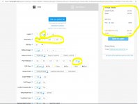
But..🙂 IF this manufacturer could be used, 20pcs of 100x250 mm double sided green 2mm boards will only cost $91.20 = $4.56 ea
PCB Prototype & PCB Fabrication Manufacturer - JLCPCB :
Designing a PCB seems to be very easy.
You need a 2 layers PCB 4oz/ft2 minimum copper thickness, 2.4mm minimum board thickness. This kind of PCB will be very expensive"
But..🙂 IF this manufacturer could be used, 20pcs of 100x250 mm double sided green 2mm boards will only cost $91.20 = $4.56 ea
PCB Prototype & PCB Fabrication Manufacturer - JLCPCB :
Attachments
Group Buy Distribution
I just sent an email and asked IF that Chinese manufacturer can manufacture boards from a Gerber file and then distribute cards to multiple recipients according to an address list.
I am sure this has been done before and maybe there is already a smart system to do this? Anyone?
(I found the manufacturer in a YouTube video. I have no connection to them whatsoever. I do not even know if they are good. But they do offer good prices, as far as I can understand.)
Last edited:
But..🙂 IF this manufacturer could be used, 20pcs of 100x250 mm double sided green 2mm boards will only cost $91.20 = $4.56 ea
PCB Prototype & PCB Fabrication Manufacturer - JLCPCB :
You forgot to set the copper thickness, and the maximum by this dealer is only 2oz/ft2 which is too thin. It must be 4oz/ft2 as a minimum. So you have to choose another dealer. The board dimensions depend on the cabinet, let's say a 400mm deep one, the board will be around 120x370mm (this board is not able to hold the output coil and its resistors and capacitors), a clever PCB designer would be able to accommodate about 8 x MJL3281A/MJL1302A final pairs.
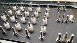
As a mechanical solution, I chose a complicated one, not mandatory in case of wired assembly, but, in case of a PCB holding the final pairs, it would be mandatory and really expensive. See the picture: an aluminum board holds all final pairs, the aluminum board is placed on top of the heat sink; the heat sink is made out of two pieces: 119 total holes, 36 x 4mm blind threaded holes on the heat sink, 47 x 3mm threaded through holes and 36 x 4.5mm not threaded through holes on the aluminum board, to hold 47 x 3mm studs and 36 x 4mm studs. all studs must be fixed with a threadlock and all studs in through holes must be tensioned during the curing time of the threadlock. The drilling and threading job must be done by a digital control machine. This design does not take into account the space among the fins of the heat sink because the threaded holes on the heat sink (base is 7mm thick) are blind. Multiply all by 2 for the two channels.
Moreover, when designing a PCB with a thick copper layer, you have to set a suitable space among tracks, bigger than the one needed with a thin copper layer, and there are a lot of constraints over the electrical ones; a good designer must take into account them all, and the client must be able to explain the designer all mechanical constraints.
I wouldn't use any PCB to hold the final pairs, which can be fixed to the heat sink by yourself: first of all you have to understand that, having only a drill, you cannot obtain threaded blind holes, then you can drill the heat sink it the space between a fin and the other (different cabinets have different heat sinks, which have different pitch, so you cannot have a PCB solution good for all), and then thread the holes, the only difficulty is to avoid breaking the tap while threading the holes. Or, perhaps better, you use flat-head screws avoiding to thread the holes. This is a very simple inexpensive job with a better sound quality.
Attachments

Last edited:
Simplified mounting
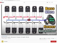
So if I used 8 x MJL3281A/MJL1302A as output pairs I could simply place them in two rows opposite each other on a heatsink with the resistors connected like a guy has done in this clip from YouTube?
Bass Ulta Power Amplifier 1000 watt with 12 Transistor - DIY Amplifier 1000 watt - YouTube
Let's disregard the cardboard 🙂 But the connections are just like in your more advanced design? :
Attachments
Last edited:
A simple but more elegant solution
This looks a bit better than in the previous movie 🙂 :
Diy 1000 Watts Mono High Power Amplifier Using Transistors 2SC5200 and 2SA1943 - V1 - YouTube
It should be possible to mount the power resistors on a predrilled board
This looks a bit better than in the previous movie 🙂 :
Diy 1000 Watts Mono High Power Amplifier Using Transistors 2SC5200 and 2SA1943 - V1 - YouTube
It should be possible to mount the power resistors on a predrilled board
Last edited:
Servo or No Servo
I would not know what to test regarding the servo, but if I do not need one (nor a Supercap?) so much the better! But without a Servo would I not need to keep the input potentiometer P1 that adjusts the DC Bias? I noticed it was omitted in your modified schematic."I would not integrate the servo in the PCB because my WHA-217 has a stable offset of 1mV. I used the servo because I didn't extend my rehearsal session, but you could deepen yours and decide.
"
Last edited:
Q13 and Q14 placement?
Marigno, are the two transistors marked with red text the Q13 and Q14 from your schematic?
If so, along with two simple rows of TO264 transistors and with no need for a Servo (nor a Supercap?) your WHA-217 modifications all of a sudden feel much simpler to grasp and to build! 🙂
Marigno, are the two transistors marked with red text the Q13 and Q14 from your schematic?
If so, along with two simple rows of TO264 transistors and with no need for a Servo (nor a Supercap?) your WHA-217 modifications all of a sudden feel much simpler to grasp and to build! 🙂
Attachments
Last edited:
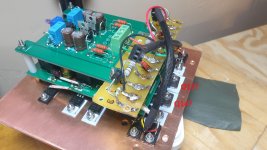
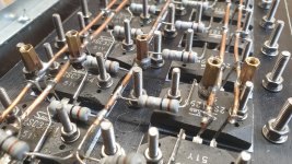
The solutions in the video clips are, more or less, what I did. But you need a thicker copper wiring, 12AWG for both emitter resistors and collectors, 14AWG for the bases without any resistor. The reason, over that an obvious lower resistance, is that you need a good mechanical strength when connecting the power wires to these bare copper wires. Zoom my last picture on the low right corner, where the alligator clips connects to the negative branch: you see a brass spacer nut soldered to the negative bare copper wire; now look to the pic I enclosed here and you will see 5 brass spacers nuts used to connect the wired assembly to the mainboard. Do not solder wires to the bare copper wires, you are an experimenter, who knows how many times you'll have to connect and disconnect the wires.
I told to try without a servo and see what is the offset and how much it is stable. The red new resistor 100KOhm connected after the input cap to GND defines the DC working point of the whole assembly to some voltage close to 0, mine is 1mV stable after 20 minutes open air. But, to decide, you have to try after 1 hour of high power listening, once the cabinet is closed. The DC protection, you must use one, should protect your speaker. Or use a dummy load. I don't have a dummy load and had no time to conduct this test, so I used the servo.
Yes, they are Q13 and Q14.
Attachments
Last edited:
2oz/ft2 after all?
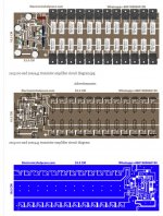
2sc5200 and 2sa1943 transistor amplifier circuit diagram - Electronics Help Care
Maybe even I, with Zero experience, could design the portion of a board that includes your RED modifications after the Q13 and Q14 transistors, including power transistors, temperature sensors, output coil, resistors and capacitors. I e most of your WHA-217 if it is combined it with a slightly modified Chinese NHB 108 board, as per your description. If 2oz/ft2 boards could be used the WHA-217 "Extension card" would not be expensive if ordered from the Chinese company I referred to in an earlier post. PCB Prototype & PCB Fabrication Manufacturer - JLCPCB
What IF 🙂 one used these very wide tracks, do you think 2oz/ft2 could work, after all?:You forgot to set the copper thickness, and the maximum by this dealer is only 2oz/ft2 which is too thin. It must be 4oz/ft2 as a minimum....
2sc5200 and 2sa1943 transistor amplifier circuit diagram - Electronics Help Care
Maybe even I, with Zero experience, could design the portion of a board that includes your RED modifications after the Q13 and Q14 transistors, including power transistors, temperature sensors, output coil, resistors and capacitors. I e most of your WHA-217 if it is combined it with a slightly modified Chinese NHB 108 board, as per your description. If 2oz/ft2 boards could be used the WHA-217 "Extension card" would not be expensive if ordered from the Chinese company I referred to in an earlier post. PCB Prototype & PCB Fabrication Manufacturer - JLCPCB
Attachments
Last edited:
Technical Mr Iganka
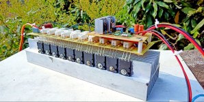
..has already made a parallel power transistor board that may work as part of a WHA-217 mod:
1000 Watts R.M.S Mono power Amplifier using 2SC5200 & 2SA1943. Technical Mriganka. - YouTube
Just imagine a modified Chinese NHB-108 on top of that assembly!
Here is a pdf of the PCB 🙂 :
1000 watts true R.M.S amplifier. Technical Mriganka - Google Drive
Can this be modified into a Gerber file?
Actually, Mr Iganka etched his pcb in ferric chloride [FeCl3+H2O] 🙂
And IF the copper is on the thin side I think it works anyway if the tracks are flooded by solder..
Attachments
Last edited:
I saw all documents you posted. I must say I don't like any represented solution.
I expressed my opinion yet, and I'm not going to change my mind towards something I repute not suitable to connect high current lines.
Your solution about the PCB, if you decide in this way, must be compatible with your mechanical arrangement, that I don't know.
I expressed my opinion yet, and I'm not going to change my mind towards something I repute not suitable to connect high current lines.
Your solution about the PCB, if you decide in this way, must be compatible with your mechanical arrangement, that I don't know.
Ok! I hear you.
I am planning to attach all power transistors to aluminum bars or L-profiles that are screwed onto the heat sinks using only a few screws (and heat transfer paste). I do not want to drill too many holes in the actual heat sinks, should this project not work out well for me. If I decide use L-bars the mounting of power transistors would be similar to the ones in a couple of the movies.
I am planning to attach all power transistors to aluminum bars or L-profiles that are screwed onto the heat sinks using only a few screws (and heat transfer paste). I do not want to drill too many holes in the actual heat sinks, should this project not work out well for me. If I decide use L-bars the mounting of power transistors would be similar to the ones in a couple of the movies.
Last edited:
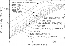
The L angular is the only mechanical solution to connect the board to the heat sink. But this solution will take out a lot of room inside your cabinet. The common aluminum alloys you can find are 6061 and 6063, you have to chose the 6063, a good thermal conductor, and avoid the 6061, look at the chart here enclosed. When the angle is internally smoothed, usually (but not always) it is a 6063 alloy. Our interest is over the right upper angle but you can understand the trend.
Attachments
Last edited:
I was thinking of buying a regular 40x40x4mm aluminum L profile:
Aluminium vinkelprofil EN6082-T6 40x40x4
Do think that will work?
Aluminium vinkelprofil EN6082-T6 40x40x4
Do think that will work?
Hi guys,
Meanwhile I have learned how to make perfect M3 threads into aluminium heat sink.
The best solution is to fix transistors on the heat sink and use alumina pads, for the maximum heat transfer.
The trick is:
1. use good drill taps according to the DIN 352
2. and even more importantly: LUBRICATE while making threads, profusely. I use WD40 or MIG welding liquid.
3. remove sawdust, every few revs, go back every few revs with the drill tap to remove aluminium particles from the hole. In contrast to steel or iron aluminium tends to agglomerate and the drill tap gets stuck and eventually breaks.
Drill taps.
Now, making good M3 treads into aluminium is so easy and heat sinks work much better.
Last edited:
I was thinking of buying a regular 40x40x4mm aluminum L profile:
Aluminium vinkelprofil EN6082-T6 40x40x4
Do think that will work?
You say, in the name of the link, it is a 6082 alloy, but the link resolves to a 6060 alloy. They are different.
To answer your question google "aluminum 6060 thermal conductivity", varying the "6060" with other alloy codes: a result of 200 W/m K as a minimum starts to be good, while copper shows 385 W/m K.
I have both 6063 and 6061 5.08 sides x 6.3mm thickness angular bars and I could observe a very different thermal behavior among them.
I would choose at least 5mm thickness, the usual is 6.3mm.
Last edited:
- Home
- Amplifiers
- Solid State
- Dartzeel amp schematic - build this?