One caveat for using the B1 Korg with this amplifier is that too much H2 may be detrimental to the sound. At low power output the amplifier's distortion level is low but at higher output the distortion rises. Combined with the B1 Korg's distortion, it may be too much.
However the B1 Korg distortion can be adjusted so perhaps an acceptable level may be determined that meets the listener's speaker's sensitivity and music sound level, and personal preference.
However the B1 Korg distortion can be adjusted so perhaps an acceptable level may be determined that meets the listener's speaker's sensitivity and music sound level, and personal preference.
No problem. Combined with your K180 inductor topology, the Korg B1 can be set to reduce, be neutral or add to the final H2.
Korg B1 H2 + any Amp tuned for higher H2 will result in H2 of H2. It's not quite the same. And you flout the basic principle that Nelson advocates that you do it only once in your audio gear chain.
No reason not to try it though.
On principle I favor the "single voice" approach.
On the other hand, I have reports of people liking the
effect of two 2nd harmonic distortion generators in series.
It is not clear whether they are adding or canceling...

On principle I favor the "single voice" approach.
On the other hand, I have reports of people liking the
effect of two 2nd harmonic distortion generators in series.
It is not clear whether they are adding or canceling...
Like Srajan Ebaen. 6moons audio reviews: FirstWatt SIT-1 with a 10Y DHT into the SIT1.
Technically, the Nutube is also a DHT, pairing it to the K180 is a great idea.
Technically, the Nutube is also a DHT, pairing it to the K180 is a great idea.
B1K preamplifier has trimmers for adjustments for less or more H2 and phase ,
you can easily find the best sound spot together with the 2SK180 power amplifier.
Tokin SIT have gain ~ 20dB (+-) so can work good with Korg
you can easily find the best sound spot together with the 2SK180 power amplifier.
Tokin SIT have gain ~ 20dB (+-) so can work good with Korg
Hello,
I'm also building choke loaded L'Amp with THF-51S and I've a B1K fot it and I'd like to try.
The current limit of my chokes is 5A, anyone have tested a good (low distortion) and sure high current working point for THF-51S, the supply is 24V like in the original project?
I'm also building choke loaded L'Amp with THF-51S and I've a B1K fot it and I'd like to try.
The current limit of my chokes is 5A, anyone have tested a good (low distortion) and sure high current working point for THF-51S, the supply is 24V like in the original project?
Your power supply voltage may be a limiting factor in trying to find a high current operating point that will yield low distortion. Previous projects with 24V supplies run at about 1.8A, I believe. And the BAF2015 with THF-51S/Singing Bush was in the neighbourhood of Vds=35V and Iq=2.3A.
However these numbers are not exact as the Tokins vary from sample to sample, but they will do if you do not have the ability to check for yourself.
Here is a sample set of curves of a THF-51S:
Tokin SIT low voltage high current curves
The ideal operating point is in an area where the Vgs curves are straight, parallel, and evenly spaced. However in real life that doesn't happen so compromises need to be made.
The best strategy is probably to build and test as I did, and do not limit yourself to a 24V supply if you want higher power output. 🙂
Peter, I see what makes you worry. In case you think that a <=150 ohm output impedance is really needed, the 100 ohm output resistor of Korg B1 can be replaced with 82 ohm.
or with 0 ohms
🙂
That's very cool.
Will try it.
Thanks.
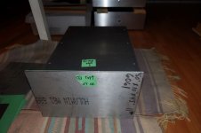
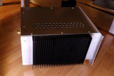
This post is about the monoblock chassis that I built for the amps. I had never built a chassis from scratch before, so this was a first for me since I could not find any commercially produced chassis that fitted my needs. I wanted two monoblock chassis with heatsinking on one side only, and the heat sink had to be able to dissipate quite a bit of heat.
The first consideration was the amount of heat that needed to be dissipated. The 2SK180 is a 300W device. Many advocate keeping maximum dissipation to 25% of rated dissipation for longevity of devices. However this is diy and pushing it a bit is only at the diyer's risk. Keeping the device cooler by providing more cooling/heat sinking would lower the risk.
So I decided to size the heat sink for at least 100W dissipation (in the end I only needed 88W dissipation). Assuming a maximum ambient temperature of 25 degrees Celcius and maximum heat sink temperature of 55 degrees Celcius, minimum heat sink requirement was (55-25)/100W = 0.30C/W. However this number is good for guidance only since published data for heat sinks, that is if you can find any information, usually do not specify the conditions for which they are valid. Information such as temperature differential is crucial. Many if not most heat sink data are based on a much higher temperature differential than the 30 degrees Celcius that I was aiming for. Therefore the manufacturer's number needed to be derated. Additionally the manufacturer's number my be or is probably based on fairly uniform distribution of heat sources throughout the heat sink. For this amplifier, there will only be one heat source on the heat sink. So again the manufacturer's number needed to be derated.
In the end I chose the Modushop 300mm x 200mm heat sink with a rating of 0.18C/W, compared to my minimum requirement of 0.30C/W.
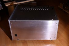
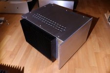
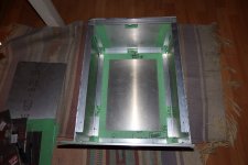
With the heat sink decided, I sized the monoblock chassis. Basically I eyeballed it based on my previous experience. I decided to be generous on the size since many of my past builds have had components tightly crammed into just barely large enough boxes. The 200mm (8") heat sink height dictated the chassis height, and I decided on a width of 12" and depth of 16".
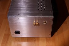
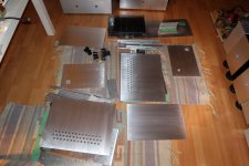
Except for the front panel, all panels were 1/8" aluminum, with 1/4" aluminum for the front. 3/4" x 3/4" x 1/8" angles were used for connect all of the panels at corners, with M3 screws into tapped holes. A 2 1/2" x 2 1/2" x 1/4" x 6" long angle was chosen for the 2SK180 attachment to the heatsink. This was attached to the heat sink with six M4 screws.
I ordered all of the aluminum online from a supplier here in British Columbia. After picking it up at the post office outlet and then after a very uncomfortable walk home (it got heavier and heavier after each step), I examined all of the pieces and found that all of the panels were not exactly square, and panels that should be identical were not. There were cutting tolerances of a few millimeters in every which direction. In the end I nudged and tweaked the fitment of the pieces and managed to put the pieces together to form two reasonably square and decent looking chassis.
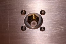
Also the back panel was supposed to be 1/8" plate, but I was sent 1/4" plate. That made cutting the opening for the IEC jack a lot more difficult. I ended up drilling a series of overlapping holes and then using a rotary tool with cutting disc to remove material for the hole, and then finished it with a file. The plate thickness was also a problem for the RCA connector. The connector was not longer enough so I drilled an oversized hole, mounted the RCA jack on a piece of light gauge steel plate, and attached the whole assembly onto the the back plate with the RCA connector centred within the oversized hole.
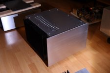
The chassis are now complete, with just a bit more sanding to do once the electronics and wiring are done.
All work was done using hand held tools. I do not have a drill press nor do I have room for a drill press. The work was tedious but quite manageable. I will do it again if I need another chassis or two, especially if a commercial chassis does not fit my needs.
The first consideration was the amount of heat that needed to be dissipated. The 2SK180 is a 300W device. Many advocate keeping maximum dissipation to 25% of rated dissipation for longevity of devices. However this is diy and pushing it a bit is only at the diyer's risk. Keeping the device cooler by providing more cooling/heat sinking would lower the risk.
So I decided to size the heat sink for at least 100W dissipation (in the end I only needed 88W dissipation). Assuming a maximum ambient temperature of 25 degrees Celcius and maximum heat sink temperature of 55 degrees Celcius, minimum heat sink requirement was (55-25)/100W = 0.30C/W. However this number is good for guidance only since published data for heat sinks, that is if you can find any information, usually do not specify the conditions for which they are valid. Information such as temperature differential is crucial. Many if not most heat sink data are based on a much higher temperature differential than the 30 degrees Celcius that I was aiming for. Therefore the manufacturer's number needed to be derated. Additionally the manufacturer's number my be or is probably based on fairly uniform distribution of heat sources throughout the heat sink. For this amplifier, there will only be one heat source on the heat sink. So again the manufacturer's number needed to be derated.
In the end I chose the Modushop 300mm x 200mm heat sink with a rating of 0.18C/W, compared to my minimum requirement of 0.30C/W.
With the heat sink decided, I sized the monoblock chassis. Basically I eyeballed it based on my previous experience. I decided to be generous on the size since many of my past builds have had components tightly crammed into just barely large enough boxes. The 200mm (8") heat sink height dictated the chassis height, and I decided on a width of 12" and depth of 16".
Except for the front panel, all panels were 1/8" aluminum, with 1/4" aluminum for the front. 3/4" x 3/4" x 1/8" angles were used for connect all of the panels at corners, with M3 screws into tapped holes. A 2 1/2" x 2 1/2" x 1/4" x 6" long angle was chosen for the 2SK180 attachment to the heatsink. This was attached to the heat sink with six M4 screws.
I ordered all of the aluminum online from a supplier here in British Columbia. After picking it up at the post office outlet and then after a very uncomfortable walk home (it got heavier and heavier after each step), I examined all of the pieces and found that all of the panels were not exactly square, and panels that should be identical were not. There were cutting tolerances of a few millimeters in every which direction. In the end I nudged and tweaked the fitment of the pieces and managed to put the pieces together to form two reasonably square and decent looking chassis.
Also the back panel was supposed to be 1/8" plate, but I was sent 1/4" plate. That made cutting the opening for the IEC jack a lot more difficult. I ended up drilling a series of overlapping holes and then using a rotary tool with cutting disc to remove material for the hole, and then finished it with a file. The plate thickness was also a problem for the RCA connector. The connector was not longer enough so I drilled an oversized hole, mounted the RCA jack on a piece of light gauge steel plate, and attached the whole assembly onto the the back plate with the RCA connector centred within the oversized hole.
The chassis are now complete, with just a bit more sanding to do once the electronics and wiring are done.
All work was done using hand held tools. I do not have a drill press nor do I have room for a drill press. The work was tedious but quite manageable. I will do it again if I need another chassis or two, especially if a commercial chassis does not fit my needs.
Attachments
-
 rough chassis.JPG230.1 KB · Views: 849
 -
 RCA in one quarter inch panel.jpg614.6 KB · Views: 353
 -
 finished chassis 5.jpg441 KB · Views: 313
 -
 finished chassis 4.jpg363.4 KB · Views: 313
 -
 finished chassis 3.jpg362.8 KB · Views: 350
 -
 finished chassis 2.jpg398.4 KB · Views: 792
 -
 finished chassis 1.jpg367.8 KB · Views: 803
 -
 chassis pieces.jpg534.6 KB · Views: 829
 -
 rough chassis-inside.jpg508.7 KB · Views: 828


Thanks everyone for your encouraging comments.🙂
ZM, my drill is handy.😀
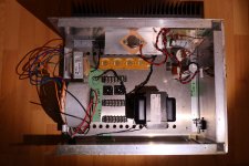
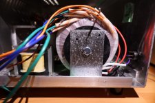
I have all the parts for the power supplies so the final push is on. Here is a shot of the power supply component layout, ready for more drilling.
Also the Simpson StrongTie A24 bracket (or similar by other manufacturers) is a great transformer vertical mounting bracket, available at local hardware stores.
ZM, my drill is handy.😀
I have all the parts for the power supplies so the final push is on. Here is a shot of the power supply component layout, ready for more drilling.
Also the Simpson StrongTie A24 bracket (or similar by other manufacturers) is a great transformer vertical mounting bracket, available at local hardware stores.
Attachments
- Home
- Amplifiers
- Pass Labs
- 25W Single Ended Hammond 193V Choke Loaded 2SK180 L'Amp