Great moment ! Safety earth connected to the chassis is a good thing. There are many ways of doing things on grounding and many articles are handling this.
Personally I connect the ground of the power supply at the supply it self to the chassis. that is the only connection. Audio outputs are "floating"
I did it the same way (PE only connected to the psu chassis). But I just saw that I connected pin 1 on the Xlr to my dac’s ground. Is there a reason you float the balanced connection or is it just because in the schematics you go from balanced to unbalanced between dac and pre? So would you recommend connecting ground to pin 1 if one has balanced pre inputs?
Greetings
Oli
I just saw that I connected pin 1 on the Xlr to my dac’s ground. Is there a reason you float the balanced connection or is it just because in the schematics you go from balanced to unbalanced between dac and pre? So would you recommend connecting ground to pin 1 if one has balanced pre inputs?
That's the good old "pin-1 problem". XLR pin 1 must be connected to the chassis, not audio GND! Pin 1 does not carry any audio signal.
Gyrators (or CCS) are nice if you need small footprint and low magnetic interference, but they require a substantial voltage drop to work correctly. I can't afford that in the Doede PSU.
That's the good old "pin-1 problem". XLR pin 1 must be connected to the chassis, not audio GND! Pin 1 does not carry any audio signal.
If I understand correctly the two hots (pin2 and pin3) use pin1 as the reference ground. And my dddac, like doedes, has the chassis not connected to PE. So this leaves to options: floating or ground from the psu. Chassis would be kind of floating too as the dddac chassis itself is “floating”.
Btw I had the same issue as you in finding the right choke (low dcr high inductance), easy fix was using a higher output voltage transformer (24V). Because it’s much easier to design a filter with higher resistance to drop some additional voltage than the other way around. As doede describes in his blog you just have to pay attention to where the heat dissipation is taking place (tip122...)
You will also gain much more flexibility. In my case for example I can (now that I got rid of the 7810 regulators and separated the psu for analog and digital) change my psu to choke input and add another RC-filter and still have enough voltage to drive the tents 😉
Greetings
Oli
Edit: I use the ll1694 (not enough current rating for you though )
That's the good old "pin-1 problem". XLR pin 1 must be connected to the chassis, not audio GND! Pin 1 does not carry any audio signal.
I don't want to connect the DDDAC chassis to any of the following devices because of the potential ground loop. I connect Pin 1 of the XLR connector to a bridge rectifier AC pin that is grounded to the chassis via a 100nF capacitor and 10ohm resistor. That should be enough to conduct any HF interference to the chassis GND. Now I should check if there is any HF interference when DDDAC is connected by cable to some device. The problem is that I don’t have a balanced test device.
Last edited:
If I understand correctly the two hots (pin2 and pin3) use pin1 as the reference ground.
Nope, that's not how balanced audio connections work. The audio signal is the difference between pin-2 and pin-3. They are floating, without any "reference to ground".
Think of pin-1 as a connection for the cable shielding as an extension to the shielding of the case/chassis.
And my dddac, like doedes, has the chassis not connected to PE.
Ouch! This is not safe!!! Unplug you DDDAC and connect the chassis to PE before plugging it back in. Do it NOW! Read Rod Elliots page I linked in my post above. You don't want to take the risk killing poeple (including yourself) or to set your house on fire.
Btw I had the same issue as you in finding the right choke (low dcr high inductance)...
There are plenty high-inductance chokes with lowish DCR out there, so that is not a problem. My aim is to make sure that the CLC as a whole has no tendency to oscillate without relying on the load (i.e., the regulator in this case) to dampen the oscillation. This means that the damping factor of the LC part must be > 1 (or at least close to 1). For more on this, see here. Implementing a properly damped (C)LC filter with a given attenuation requires that L < DCR² x C / 4 (with no external load on the filter). In other words, at some point it's better to increase the value of C instead of L in order to avoid oscillation.
I will use a 15 mH choke with DCR = 0.9 Ohm followed by a 28 mF capacitance (2 x 14 mF low ESR caps in parallel to optimize the high-frequency attenuation). You will see that these numbers will actually yield a "ringing" filter, but the overshoot is still very small as shown in post 8361.
I don't want to connect the DDDAC chassis to any of the following devices because of the potential ground loop.
If there is a ground loop, it will be running through the XLR shield between the chassis/PE connections of the DDDAC and the (pre)amp. In other words, the ground loop is separate from the audio signal. I'd recommend to connect the XLR pins correctly.
Thank you. I have worked like this before and there have never been any problems. My preamplifier and amplifier are also indirectly grounded to the chassis in the same way, and I've seen that many others practice it or do it grounded via NTC and the like, so this via Pin 1 would be a direct connection to home grounding. If there is a problem, it can be easily corrected, detach from one AC terminal on the bridge and solder to the other connected to the chassis. I'll try to find a balanced preamp for the test.
Last edited:
Ouch! This is not safe!!! Unplug you DDDAC and connect the chassis to PE before plugging it back in. Do it NOW! Read Rod Elliots page I linked in my post above. You don't want to take the risk killing poeple (including yourself) or to set your house on fire.
Actually that’s not true as this depends pretty much on the design, there is even floating tube preamps you can buy commercially. My dac for example has all metallic parts well isolated from anything electric 😉 But in general you are right.
I simulate all my filters with micro-cap (it’s free since a few years now and does a pretty nice job regarding splice simulations) and I had no problems with ringing (measurements confirmed in the end 😉 )
That there are enough chokes with high inductance and low dcr depends on what one regards as high inductance I guess 😀 but if you want to go into the xxx or even xxxx mH region things get difficult especially if you need t draw above xxx mA current.
Was just a tip with the higher voltage transformer as it made my life a lot easier but everybody has his own ideas about that stuff, I’m looking forward to your findings 🙂
Greetings
Oli
Hello,
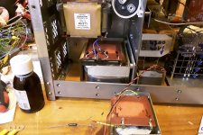
I did do some changes in the 12 volt power supply. I mean i dont use the 12 volt supply as designed by Doede but use a LCLC to create around 12,5 volts to be connected to the mainboard like other have done in this thread. It is surely more expensive. For those afraid to use a choke the expensive supply designed by Audio creative uses a choke too.
I am using a Lundahl heater power supply because it has multiple secundary windings that i needed because i wanted to adjust the AC voltage going into the SBYV28 diodes.
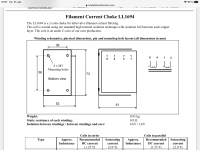
The last two years i have been using split bobbin transformers like the Triad FP30-1600 which is 30 volts 1,6A. If you use the LL2771 ( 3000mH 1A) for choke input you will get a substantial voltage drop because each coil of this choke is 5,6 ohm DCR. This Triad cost around 15 euro, With choke input NO NEED to get a 3A transformer because the choke will keep the current at 1A all the time.
Depending what you will use after the first choke and of course the load presented by the circuit itself you can also get an FP transformer with eg 24 volts.
Greetings, Eduard
I did do some changes in the 12 volt power supply. I mean i dont use the 12 volt supply as designed by Doede but use a LCLC to create around 12,5 volts to be connected to the mainboard like other have done in this thread. It is surely more expensive. For those afraid to use a choke the expensive supply designed by Audio creative uses a choke too.
I am using a Lundahl heater power supply because it has multiple secundary windings that i needed because i wanted to adjust the AC voltage going into the SBYV28 diodes.
The last two years i have been using split bobbin transformers like the Triad FP30-1600 which is 30 volts 1,6A. If you use the LL2771 ( 3000mH 1A) for choke input you will get a substantial voltage drop because each coil of this choke is 5,6 ohm DCR. This Triad cost around 15 euro, With choke input NO NEED to get a 3A transformer because the choke will keep the current at 1A all the time.
Depending what you will use after the first choke and of course the load presented by the circuit itself you can also get an FP transformer with eg 24 volts.
Greetings, Eduard
Attachments
That's a lot of iron. Is any overvoltage protection provided for the DDDAC? What happens to the DC voltage on LCLC power supply (12.5V stationary) when the device is turned on and off?
@Eduard,Would you recommend to use the chokes in common mode configuration when used in a choke input power supply. Or better “standard” series?
Hello,
There is a high power zener diode across the first cap that will keep the voltage from rising above a certain voltage.
There is a so called load/bleeder resistor that will; take of a minimum current.
There is the 7810 to protect the shunt.
The voltage rises gradually after switching on. When switching off the caps drain in a few seconds because of the current drawn by the shunt.
There is not a lot of capacitors.
As you can see i use 3,5 A rated diodes no problem because the input choke will limit the current to the nominal value presented by the circuit.
Doede simulated my present power supply and it gave very nice results.
The inductance remains the same if you connect the choke in common mode connection. Lundahl told me that it should be better and some users confirmed this. It is rather easy to test it. I never tested it.
A famous audio technician in my country told me to only use this technique for the first choke. I dont remember why and i am almost sure that he never tried it actually. He can probably explain why not to do so BUT you just have to try.
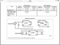
With the Lundahl chokes you MUST take care how you connect them. It doesnt matter which of the two '' coils '' is on which '' side '' of the power supply.
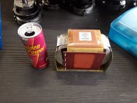
The small one is the LL2733 and the big one is the LL2771
Connections are clearly indicated in the Lundahl PDF.
Greetings, Eduard
There is a high power zener diode across the first cap that will keep the voltage from rising above a certain voltage.
There is a so called load/bleeder resistor that will; take of a minimum current.
There is the 7810 to protect the shunt.
The voltage rises gradually after switching on. When switching off the caps drain in a few seconds because of the current drawn by the shunt.
There is not a lot of capacitors.
As you can see i use 3,5 A rated diodes no problem because the input choke will limit the current to the nominal value presented by the circuit.
Doede simulated my present power supply and it gave very nice results.
The inductance remains the same if you connect the choke in common mode connection. Lundahl told me that it should be better and some users confirmed this. It is rather easy to test it. I never tested it.
A famous audio technician in my country told me to only use this technique for the first choke. I dont remember why and i am almost sure that he never tried it actually. He can probably explain why not to do so BUT you just have to try.
With the Lundahl chokes you MUST take care how you connect them. It doesnt matter which of the two '' coils '' is on which '' side '' of the power supply.
The small one is the LL2733 and the big one is the LL2771
Connections are clearly indicated in the Lundahl PDF.
Greetings, Eduard
Inspired by Doede. I installed one Lundahl 1694 choke on each 5v psu’s, which is feeding two 5v Ultra capacitor boards connected in series to get 10v for dddac mainboard with 4 dac boards.
Hi smooth dancer, I'm wondering if the Lundahl choke is connected correctly. I cannot see it good on the picture, but it seems to me that you have connected the pins 3 and 4!? This should lead to a parallel connection!?? Not sure if I'm right...
Another reason that Pin 1 should not be connected directly to the chassis of the device but to the GND from the power supply and all that indirectly to the chassis.
How to Wire an XLR to an RCA Connector
How to Wire an XLR to an RCA Connector
Hello,
It is not very clear but there have been more people who ended up with Lundahl chokes connected the wrong. SO they dont have a CLC but CRC supply
There is only one way to put the two '' parts ''in series.
There is only one way to put the two parts in parallel
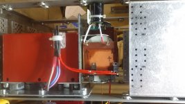
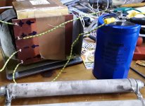
When using the '' special series connection '', number 3 in the Lundahl PDF just take a look at my picture with the BIG power resistor a few days ago. It does not matter which part of the choke is on the + or the - side. Just take care of the arrows indicating the input wire coming from the preceding element in the filter ( in my case the diodes) and the cap after the choke.
I have connected Lundahl chokes a dozens of times really and it is easy to do it wrong both in series and in parallel connection. Usually i will just use a marker. Sometimes the numbers in the pdf are a bit confusing.
Smoothdancer picture looks like connection 3 and 4 are linked which is a good '' start '' for parallel connection. What makes it confusing is the two red wires. I think the big power resistor is the bleeder resistor needed for choke input. OR is it in series with the choke?
I would put a bleeder right at the cap after the input choke.
Greetings, Eduard
P.s i asked Per Lundahl himself you cannot you one '' half '' of a choke for one 5 volt supply and the the other half for another supply. BOTH halves must get the same '' input '' to make them work like a team so to say.
It is not very clear but there have been more people who ended up with Lundahl chokes connected the wrong. SO they dont have a CLC but CRC supply
There is only one way to put the two '' parts ''in series.
There is only one way to put the two parts in parallel
When using the '' special series connection '', number 3 in the Lundahl PDF just take a look at my picture with the BIG power resistor a few days ago. It does not matter which part of the choke is on the + or the - side. Just take care of the arrows indicating the input wire coming from the preceding element in the filter ( in my case the diodes) and the cap after the choke.
I have connected Lundahl chokes a dozens of times really and it is easy to do it wrong both in series and in parallel connection. Usually i will just use a marker. Sometimes the numbers in the pdf are a bit confusing.
Smoothdancer picture looks like connection 3 and 4 are linked which is a good '' start '' for parallel connection. What makes it confusing is the two red wires. I think the big power resistor is the bleeder resistor needed for choke input. OR is it in series with the choke?
I would put a bleeder right at the cap after the input choke.
Greetings, Eduard
P.s i asked Per Lundahl himself you cannot you one '' half '' of a choke for one 5 volt supply and the the other half for another supply. BOTH halves must get the same '' input '' to make them work like a team so to say.
@nixie I think mbrennwa is right here, pin1 is a big misunderstanding, after some reading it seems that pin 1 is there to connect the chassis of the different components to each other (no audio signal involved) so if you have the dac chassis grounded(pe) pin1 should go to chassis in case of a wooden or floating chassis I’m still not so sure, depends probably on how the rest of the components connect pin1 oO
Found a pretty good article here Humming Along To The Pin 1 Problem | Tortuga Audio
I’m not so sure how this behaves when going from Xlr (balanced) to rca (unbalanced).
@eduard: thanks for the info 🙂
Greetings
Found a pretty good article here Humming Along To The Pin 1 Problem | Tortuga Audio
I’m not so sure how this behaves when going from Xlr (balanced) to rca (unbalanced).
@eduard: thanks for the info 🙂
Greetings
Last edited:
Hi smooth dancer, I'm wondering if the Lundahl choke is connected correctly. I cannot see it good on the picture, but it seems to me that you have connected the pins 3 and 4!? This should lead to a parallel connection!?? Not sure if I'm right...
Hi, you are right. Parallel it is if I understand the pic from Lundahl correctly.
Attachments
I think I will try the bleeder resistor after the choke instead of in front, as it is now. When I connect the choke in serie, the psu slowly drop it’s voltage with load connected. If I put the bleeder after the choke , maybe this will solve the voltage drop ?
Lundahls in parallel is only 0.04H, in series 0.16H, so series is better for more Henry, and better filtering, I guess.
I don’t want to change the stock trafo’s for now, so It will be either choke in series, with a bleeder after the choke. If this doesn’t work, then parallel is the only way with stock transformers, to avoid the voltage dropping.
Yesterday I removed R2 from the standard PSU and replaced it with Lundahl 1694 choke in series mode. This is really a step forward. Normally I give new setups some time because I'm not always sure if my brains fools me and lets me hear what I want to hear ;-). But this time it is clear and I'm quite sure that the choke will stay in the PSU...
Maybe I'll replace the cap after the choke (C3) with a bigger C the next days to see if there is another improvement.
Maybe I'll replace the cap after the choke (C3) with a bigger C the next days to see if there is another improvement.
eduard@
The bleeder resistor is before the choke, I will try it out after the choke, so it can draw current out from the choke. I remember Per Lundahl told me this will gelp the choke doing it’s job better.
The bleeder resistor is before the choke, I will try it out after the choke, so it can draw current out from the choke. I remember Per Lundahl told me this will gelp the choke doing it’s job better.
- Home
- Source & Line
- Digital Line Level
- A NOS 192/24 DAC with the PCM1794 (and WaveIO USB input)