Use C0G or NP0 ceramic instead. There is no discernible difference.
Edit: Here’s a good article on caps:
Measured Differences Between Capacitors for Audio Applications
NP0 and C0G are every bit as good as mica, albeit at lower voltages. Do use 100V or higher.
Edit: Here’s a good article on caps:
Measured Differences Between Capacitors for Audio Applications
NP0 and C0G are every bit as good as mica, albeit at lower voltages. Do use 100V or higher.
Last edited:
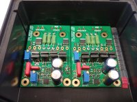
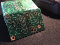
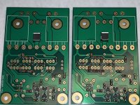
My PCBs also finally arrived 🙂
Not all the components are here yet, but that will also change shortly.
Hi Kn0ppers,
I hope you still agree to sell me a pair!
My latfets are warming up already 🙂
Cheers,
Jacques
Attachments

Your Exicon FETs have dots!
I'm really stoked by the level of interest in this little amp. It's certainly my favourite of the AEM6000 based ones.
I'm really stoked by the level of interest in this little amp. It's certainly my favourite of the AEM6000 based ones.
Your Exicon FETs have dots!
I'm really stoked by the level of interest in this little amp. It's certainly my favourite of the AEM6000 based ones.
Hi Suzyj,
The dots refer to 'S' variants specifically selected by Exicon to be used in parallel.
I can't wait to test your interesting design

Cheers,
Jacques
Happy New Year everyone! 🙂
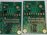
What better way to ring in the new year than to start a new amp project. I made some progress today, all the SMD soldering is completed.
What better way to ring in the new year than to start a new amp project. I made some progress today, all the SMD soldering is completed.
Attachments
Happy New Year everyone! 🙂
What better way to ring in the new year than to start a new amp project. I made some progress today, all the SMD soldering is completed.
Happy New Year Vunce

Nice job! Did you use hot gun or oven reflow?
Thanks Suzy!
I’m using Susumu RG 10ppm resistors in those two locations.
https://www.mouser.com/ProductDetail/Susumu/RG2012N-102-B-T5/?qs=01v%2BktAZElahpLZh1XxlPw==
https://www.mouser.com/ProductDetail/Susumu/RG2012N-153-D-T5/?qs=01v%2BktAZElZEg5q%2BpAaTeA==
Looking forward to powering the boards up and hearing first sound from these little guys 🙂
Hi Jacques,
SMD soldering method:
I use a hot plate with a pan to preheat the pcb, then use a hot air pencil from the top to flow the solder.
All the components larger than the MELF resistors were soldered with a fine tip iron. You must be very careful not to overheat the CDE film caps, heat is their enemy. Apply a bit of flux and get in and out quickly.
Enjoy your build,
SMD soldering is therapeutic 😉
Here's how I do it:
Soldering MELF resistors with a soldering iron - YouTube
Apologies for the faffing around in the video. I was trying to be brief, but these things never work out that way.
I start with a tiny dab of flux from a syringe, then tin one pad, hold the component with the right tweezers while reflowing the tinned pad, then spin it around and solder the other side.
It's very fast for prototyping, and has lots better control than hotplates or hot air.

Thanks Suzy: the video is very helpful. It looks so easy!
I also just purchased the notched tweezers you recommend in the construction notes.
Cheers,
Jacques
I also just purchased the notched tweezers you recommend in the construction notes.
Cheers,
Jacques
I use the same technique as Suzy, but I keep my soldering iron tip cleaner. I also use a liquid rosin flux. I learnt to solder SMD with a hot plate and hot air but never use that technique any more.
Agreed, do it the same way as Suzy. The hot air station is reserved to de-soldering jobs only. Having SMD-parts with extra fat pads for handoldering in my KiCAD-lib.
anyone having 2 pair SST404-LF left for me ?
These devices appear to be the Achilles heel of this design. I bought 10 of them and the shipping was more costly than the devices themselves. All of mine appear to be accounted for at this point in time. I should have bought a lot more to bring down the average cost per device.
PS. I just looked at their website and they offer free shipping on orders above $60 into Australia. My order came to $54 😡 I wish this was more obvious when I placed my order.
See: Shipping & Delivery | Futureelectronics NorthAmerica Site
Last edited:
- Home
- Amplifiers
- Solid State
- AEM6000 Based 50W Amp