Hello everyone,
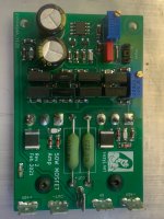
After a long time I’ve finally finished building Suzy’s 50 W Rev. 2 amplifier. I’m pleased to say the sound is really beautiful, especially in the vocal frequencies. However, my own measurements with my Quantum meter don’t quite match Suzy’s published figures. Could I be making a mistake somewhere? Any insights or suggestions would be greatly appreciated!
Power supply:
2 × 40 VDC (from a 2 × 30 VAC, 250 VA transformer)
35 A bridge rectifier
5 × 4700 µF reservoir caps
Below are my measurements at two bias settings:
11mV output bias

24mV output bias

Output noise (input shorted)

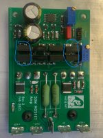
After a long time I’ve finally finished building Suzy’s 50 W Rev. 2 amplifier. I’m pleased to say the sound is really beautiful, especially in the vocal frequencies. However, my own measurements with my Quantum meter don’t quite match Suzy’s published figures. Could I be making a mistake somewhere? Any insights or suggestions would be greatly appreciated!
Power supply:
2 × 40 VDC (from a 2 × 30 VAC, 250 VA transformer)
35 A bridge rectifier
5 × 4700 µF reservoir caps
Below are my measurements at two bias settings:
11mV output bias
24mV output bias
Output noise (input shorted)
Attachments
If you have not seen it, Bob Cordell has written a tutorial on using the QA403. I no longer have an amp with Susy's circuits so I cannot take a measurement for comparison. However, I was able to lower the measured distortion, effectively adding another zero, by adding back the driver stage differential.

Your distortion is dominated by H2. I found with my amps that when I got lots of even distortion products it was because I'd stuffed up something on one side. As an example one time I didn't bolt one of the mosfets down correctly.
See https://www.suzyj.net/2017/01/measuring-mosfet-power-amplifier.html
Another one that caused me a lot of grief was using crappy thick-film resistors in the feedback divider.
See https://www.suzyj.net/2017/01/measuring-mosfet-power-amplifier.html
Another one that caused me a lot of grief was using crappy thick-film resistors in the feedback divider.
Last edited:
Also, where are you measuring? You've gotta measure across the speaker outputs. Measuring between the speaker +ve and some other ground will give excess H2, plus lots of 50Hz harmonics, which I see you have. Remember the feedback divider samples from where the speaker connects.
Hi Suzy
My all components are from mouser and profusion. Nfb resistors are thin film vishay melf. Everything is as your discrebed. I have to admid this amplifier have so good sound for me. İmportant be this for me. So i build its 100w versions. I just wonder of it, what could be diffrent with your measurements and my measurements.
My all components are from mouser and profusion. Nfb resistors are thin film vishay melf. Everything is as your discrebed. I have to admid this amplifier have so good sound for me. İmportant be this for me. So i build its 100w versions. I just wonder of it, what could be diffrent with your measurements and my measurements.
If you have not seen it, Bob Cordell has written a tutorial on using the QA403. I no longer have an amp with Susy's circuits so I cannot take a measurement for comparison. However, I was able to lower the measured distortion, effectively adding another zero, by adding back the driver stage differential.
What did you mean?
by adding back the driver stage differential.
kr
chris
Last edited:
Sorry if this is a dumb question, but why use a 0R resistor for R2, R15 and R16? Why not just wire?
From your perspective there is no difference.
It might be due to the way the board layout software handles jumpers, or to accommodate automated board stuffing.
It might be due to the way the board layout software handles jumpers, or to accommodate automated board stuffing.
it is for testing the IPS - input stage.Sorry if this is a dumb question, but why use a 0R resistor for R2, R15 and R16? Why not just wire?
if everything is fine then you can solder a bridge = 0R esistor
my guess
chris
R2 allows me to sample the gnd for the feedback patch from the speaker -ve terminal, hence the two grounds.
R15 and R15 may be removed, and then the input stage can be driven from an independent power supply higher than that used for the output, allowing higher efficiency (clipping closer to rail) with a lot more power supply complexity.
R15 and R15 may be removed, and then the input stage can be driven from an independent power supply higher than that used for the output, allowing higher efficiency (clipping closer to rail) with a lot more power supply complexity.
I really want to try your amp because, measurements aside, this amp has a good sound. What do you recommend for running your amp at 100w? Also, it's true that the amp's transistors don't get hot, but shouldn't all transistors be connected to the same heat sink for thermal balance and distortion?The attached schematic is essentially the original 6000 circuit but with more modern components. The protection circuit monitors the servo output and will trip when it gets close to a rail, indicating too much DC is present. The amp itself simulates very nicely. Perhaps not quite as low a THD value as more significant changes deliver but very respectable (single digit ppm
I have attached a simulation with +/-50V rails that would hit the 100W mark. I used two FETs in parallel but with a common source resistor to mimic an Exicon FET. Driver transistors dissipate over 500mW so they would need a heatsink plate. I do not think placing the drivers on the main heatsink offers improved performance (lower distortion), but it does offer an excellent way to dissipate their heat. There is probably still an optimization to be made with the current the VAS stage runs at.
Attachments
I made up a relay board that would allow switching between the outputs of two amps instantly (okay, a few milliseconds). The point being to compare the "sound" of two amplifiers without relying on "aural memory" which is most likely a questionable technique.
I switched between a restored Yamaha B2 and an amp using the boards shown in post 352. The amp uses 1182F30 transformers, creating voltage rails that deliver 69 watts into 8 ohms before clipping. The FETs are NOS Renesas.
The listening was near field using high quality mini-monitors. For source material we listened to Larkin Poe and Solas. Three different listeners could hear no difference. Each listener was given the control switch so they could change amps at a point in the music of their choosing. Nobody could detect any difference.
Goes without saying that the Yamaha B2 is a legendary amp with specifications that are still the equal of many modern amps. But a bit tough to acquire one since they haven’t been built for 45 years or so. These AEM6000 derivatives are a viable alternative.
The sound of the AEM6000 is truly unique. Honestly, it's one of the best discrete amplifiers I've ever listened to. I'm currently working on a PCB for your 100W version.
By the way, did you do your listening — with the JFE2140 and servo — using your 50W version?
By the way, did you do your listening — with the JFE2140 and servo — using your 50W version?
Better to call it a single output transistor per rail design, as the wattage is of course a function of the rail voltage. But yes, it is the circuit and boards shown in post 352 which uses the JFE2140 as the input differential. Also not identical to Susyj's design in that the driver stage more closesly matches Tilbrook's design. Other posters have noted that the Exicon FETs are identical to the Hitachi/Renasas devices, but I built with the NOS Hitachi/Renesas devices.
Hmm.
Nobody? 😉
- Home
- Amplifiers
- Solid State
- AEM6000 Based 50W Amp